Before computers were broadly available for loudspeaker bass reflex box simulations, engineers relied on “Alignments” for their designs. Such box alignments are typically named after equivalent filter functions that the high-pass response of the box was aligned after — for example, Butterworth (B4) and Bessel (BL4) — to name a few. Interestingly, there are some filter functions that do not have a box alignment equivalent, for example, the Linkwitz-Riley filter response [1, 2], which is popular for electrical filters and is characterized by two cascaded identical Butterworth filters, and hence Linkwitz-Riley filters are per definition of even order. The second order is often in short form named LR2, and the fourth order is often named LR4.
On the other hand, some box alignments do not have an equivalent filter function (not used for electrical filters and crossovers), for example, the Boombox bass reflex alignment, which is characterized by two cascaded identical filters but not necessarily Butterworth filters. The bass reflex design, by principle, is of fourth order, and this alignment is named BB4.
Since the Linkwitz-Riley filter and the Boombox alignment share the characteristic property that they use cascaded identical filters, it becomes obvious that for the specific BB4 case where the second-order filters are of the Butterworth type, the response becomes equivalent to an LR4 filter response. It means the LR4 alignment has existed as a limit case of the BB4 alignment since its inception; it was just not pointed out by anyone. The author holds no claim to fame for having discovered the LR4 alignment; we can only assume that many engineers must have noticed this correlation at some point. On the other hand, we have never seen Linkwitz-Riley mentioned anywhere (except in our own work) in relation to loudspeaker bass reflex, and we are unaware of anyone who has presented the performance of the LR4 alignment.
When the BB4 alignment was originally defined by William John Joseph Hoge [3, 4], he specified that the alignment per definition must be under damped and consequently have a peak in the response. Robert M. Bullock, III [5] extended the response into the range with a linear frequency response, and he named it SBB4 (Sub-BB4).
Whereas the (S)BB4 alignment is defined for a range of loudspeaker drivers, with different Qt values ranging from, say, 0.20 and up to 0.72 (at least this is the upper limit investigated by Hoge), the LR4 response is a discrete alignment that resides exactly in the crossover between BB4 and SBB4, meaning it is only defined for a specific driver Qt value, which we will identify in this article.
The Calculation Including Leakage Loss
The fourth-order Linkwitz-Riley high-pass filter is defined as two cascaded second-order Butterworth filters:
G(s) = s4/( (s2 + 2 zeta s + 1)2)
where zeta = 1/√2 = 0.707 is the damping ratio. The filter-Q of each second-order Butterworth section is:
Q = 1/(2 zeta) = 1/√2 = 0.707
Studying work by Richard H. Small [6, 7], we can derive:
Ql = 10
Qt = 1/(sqrt(8)-1/Ql)
h = 1
alpha = 1/4 * (1/Qt - 1/Ql)^2
// Replace Vas with your driver's Vas-value
Vb = Vas / alpha
// Replace fs with your driver's fs-value
fp = h * fs
Qt = 1/(sqrt(8)-1/Ql)
h = 1
alpha = 1/4 * (1/Qt - 1/Ql)^2
// Replace Vas with your driver's Vas-value
Vb = Vas / alpha
// Replace fs with your driver's fs-value
fp = h * fs
where Qt is not something you can specify yourself but rather is given by the equations because the LR4 alignment is a discrete alignment, similar to Butterworth B4 and Bessel BL4. The port tuning ratio defined by h = fp/fs always = 1 for any (S)BB4 alignment, by definition.
The classic Thiele-Small (T-S) theory prescribes that the loudspeaker designer should account for losses by setting Ql in the range of 5 to 20, typically set conservatively to 7, but no matter what value is chosen, it is arbitrary and not based on physical leakage. In the shown code, Ql is set to 10, a round number. An even higher Ql value could be chosen, calculating a larger alpha value (smaller box volume), with a slightly increased risk that the box you build becomes a bit too small. You are welcome to change the Ql value as you see fit.
The code includes Vas and fs, but they are not defined. Either specify the values for the driver you intend to use or exclude the last two lines (plus the comments) from the code you execute in Scilab, otherwise Scilab will inform you these are undefined variables.
For leakage Ql = infinity, the driver Qt that matches the Linkwitz-Riley response function is: 1/√8 = 0.354. If Ql = 10, as in the code example, then Qt = 0.367. When aiming for these Qt values, remember that the driver specification from the datasheet should be a bit lower to allow for some series resistance.
If you have a specific driver in mind, chances are slim that it will be able to match the required Qt-value exactly, and if you measure one that matches one day, then the next day it may no longer measure the same, but if you allow some computational error, one could simply ignore that the driver at hand deviates by a few percent (e.g., 5%). Note that a 5% deviation is a small one, considering measurement tolerances and the fact that all these calculations are based on a simplified model of the driver as well as a simplified box model, and that the results may depend on, for example, the temperature of the environment. This is not accurate science. Arguably, if you allow some degree of error, even a 10% deviation in Qt can be acceptable.
Note that the calculation of h and alpha is identical for the LR4 and the BB4 alignments. When Qt is not matching the LR4 case, a simple solution is to use the BB4 alignment, where Qt may be chosen freely. You do this simply by replacing Qt = 1/(√8-1/Ql) with the actual Qt-value of the driver. One should expect similar behavior in both frequency response and phase response (and group delay) if the driver Qt is close enough to the LR4 target.
Evaluation
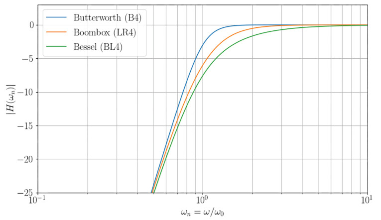
From Figure 1 and Figure 2, we can see that the performance of the LR4 alignment is quite good. It doesn’t extend as far down in frequency as the Butterworth (nothing linear will do that; only nonlinear alignments will go deeper than Butterworth), but it does play a fair amount more bass than the Bessel alignment.
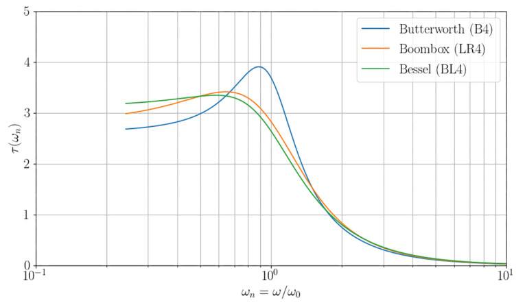
On the other hand, the group delay plot (Figure 2) shows that the LR4 is almost as good as the Bessel alignment in this respect. Group delay is a computation of the rate of phase change versus frequency, it is a metric for phase distortion (although not the only one), and it therefore quantifies the distortion of impulses due to these phase changes. It is thus to be expected that a bass reflex system tuned to the LR4 alignment will perform quite well with impulsive bass. Although the group delay is higher than for the Butterworth alignment below ca. 0.65 × the system resonance frequency (i.e., well into the stop-band where the level is now around -15dB), the group delay is quite flat, not peaky, which is desirable.
We have defined the LR4 alignment for lossy bass reflex designs. Allowing for some alignment error, it is fair to conclude that driver Qt in the range of 0.34 to 0.40 is feasible for the implementation of a bass reflex system with approximately an LR4 response.
The alignment can be useful for anyone who wants to enjoy the characteristics. Compared to a Butterworth response, one property is a less sharp roll-off (i.e., a softer knee-point), another is better impulse response with less group delay (i.e., less phase distortion of impulses). In fact, the LR4 alignment behaves somewhere between a Butterworth and a Bessel response, which in practice could be a desirable compromise.
The LR4 alignment could also prove useful if you wish to combine a main system with a powered subwoofer, and the subwoofer is electronically low-pass filtered to obtain a fourth-order Linkwitz-Riley acoustic response. By carefully matching the main system high-pass roll-off to the subwoofer, a seamless integration can be obtained without any electronic filtering of the main system, especially because the LR4 crossover was designed for non-coincident drivers, such that one of the characteristic properties of the LR4 is that the low-pass and high-pass sections add up in-phase throughout the crossover region. VC
Author Acknowledgment: Thank you to Jeff Candy, who has helped with the derivation of these algorithms, as implemented into the Alignment Chart of the Speakerbench [8] web application.
References
[1] S. H. Linkwitz, “Active Crossover Networks for Noncoincident Drivers,” Journal of the Audio Engineering Society, Vol. 24, Issue 1, pp. 2-8; January/February 1976, https://www.aes.org/e-lib/browse.cfm?elib=2649
[2] S. H. Linkwitz, “Passive Crossover Networks for Noncoincident Drivers,” Journal of the Audio Engineering Society, Vol. 26, Issue 3, pp. 149-151; March 1978, https://www.aes.org/e-lib/browse.cfm?elib=3287
[3] W.J.J. Hoge, “A New Set of Vented Loudspeaker Alignments,” 55th Audio Engineering Society Convention, Preprint no. 1144, New York; October 1976,
https://www.aes.org/e-lib/browse.cfm?elib=2270
[4] W.J.J. Hoge, “A New Set of Vented Loudspeaker Alignments,” Journal of the Audio Engineering Society, Vol. 25, Issue 6, pp. 391-393; June 1977, https://www.aes.org/e-lib/browse.cfm?elib=3364
[5] R. M. Bullock, III, “Thiele, Small and Vented Loudspeaker Design, Part IV: Alternative Alignments,” Speaker Builder magazine, Number 3 (July/August/September 1981), pp. 18-27.
[6] R. Small, “Vented-Box Loudspeaker Systems - Part I: Small-Signal Analysis,” Journal of the Audio Engineering Society, Vol. 21, Issue 5, pp. 363-372; June 1973, https://www.aes.org/e-lib/browse.cfm?elib=1967
[7] R. Small, “Vented-Box Loudspeaker Systems Part IV: Appendices,” Journal of the Audio Engineering Society, Vol. 21 Issue 8, pp. 635-639; October 1973,
https://www.aes.org/e-lib/browse.cfm?elib=1941
[8] Speakerbench, https://speakerbench.com
Appendix
In the work by Dr. Richard H. Small, it is argued that one may lump absorption losses (Qa) and port losses (Qp) into leakage losses (Ql). It seems the classical choice of setting Ql = 7 (or 10, or whatever) is promoted not for being correct but for being a convenient and practical way to work with the fourth-order transfer function and sticking to the fourth-order function since leakage is a resistive loss (constant with frequency). This approach ignores other losses (e.g., viscoelastic losses in the driver, which is a frequency-dependent loss).
With advanced measurement and simulation capability available today, it is possible to improve on this, which most notably implies lumping of losses is not necessary anymore. Bear in mind that the alignment theory presented here continues with a simplified analysis where Ql is a lumped parameter, just because this is how the alignment theory was established and because the theory is easy to communicate.
This article was originally published in Voice Coil, June 2024