Brief Recap
Before computers were broadly available for loudspeaker bass reflex box simulations, engineers relied on “Alignments” for their designs. Such box alignments are typically named after equivalent filter functions that the high-pass response of the box was aligned after, for example, Butterworth (B4) and Bessel (BL4), to name a few.
The Inter-Order Butterworth filter response was mentioned briefly by Richard Small [2], where he references an unpublished article. Unfortunately, I couldn't find a published article with that name. Robert Bullock [3] must have found the correct article or, alternatively, been in contact with Neville Thiele or Richard Small, but his article series in Speaker Builder magazine didn’t contain any references. To find more information, I scanned all the materials published by Thiele and found an article [4] with the desired content. The article isn’t in the public domain but had to be ordered (in this case from the Royal Danish Library in Aarhus, price ca. $15 US).
However, Thiele’s article doesn’t provide the required normalized high-pass polynomial directly, but rather a normalized equation relative to the -3dB point, which is compared to third- and fourth-order Butterworth filters. This filter function lies between these two in the area of the roll-off knee point, and hence Thiele named it a 3-1/2 order, as does Bullock.
Thiele was targeting electronic filters, possibly for assisted bass reflex alignments, and he realized that both 3-1/2 and 5-1/2 orders are possible solutions. It is thanks to Bullock that this alignment is not forgotten and that it is considered an option for passive loudspeaker designs (without electronic assistance), but then only the 3-1/2 order is realizable.
The Thiele Inter-Order Butterworth response is also referenced in the Loudspeaker Design Cookbook by Vance Dickason [5], here named IB4. Bullock also used the IB4 acronym. I think it is appropriate to name it a fourth-order response and have chosen to adapt this name.
The Calculation Including Leakage Loss
The fourth-order Inter-Order Butterworth high-pass filter is defined by Thiele as a combination of a second-order and two identical first-order filters:
G(s) = s^4 / ( (s^2 + 2 kappa s + lambda) * (s + 1)^2 )
For our application, the polynomial must be manipulated into a suitable normalized form for identification of the polynomial coefficients, which is achieved when kappa = √(2 * (√(3) - 1)) and lambda = √(3). With the mentioned special coefficients, the polynomial coefficients a1, a2, and a3 and the normalized response function can be calculated. The generalized expression is:
G(s) = s^4 / (s^4 + a1 s^3 + a2 s^2 + a3 s + 1)
The coefficients of the normalized polynomial based on kappa and lambda are calculated in the algorithm below. Studying work by Small [1, 6], we proceed by solving for the positive real root using Scilab:
Ql = 10
kappa = sqrt(2 * (sqrt(3) - 1))
lambda = sqrt(3)
a1 = (2 + kappa) / lambda^0.25
a2 = (1 + 2 * kappa + lambda) / sqrt(lambda)
a3 = (kappa + 2 * lambda) / lambda^0.75
Qt = 1./(sqrt(a1*a3) - 1/Ql)
function y=f(x)
y=x^4-a1*Ql*x^3+a3*Ql*x-1;
end
// Solve for positive real root near r = 1
r=fsolve(1,f)
h = r^2
alpha = a2*h - h^2 - 1 - (a3 * sqrt(h) * Ql - 1)/Ql^2
where Qt is not something you can specify yourself but is given by the equations because the IB4 alignment is a discrete alignment, similar to Butterworth B4, Linkwitz-Riley LR4, and Bessel BL4. The Qt, h, and alpha values may be compared to the results in Bullock’s alignment table XIX. For Ql = 10, the IB4 Qt = 0.3518, just about 4% lower than the LR4 Qt.
The classic Thiele/Small theory prescribes that the loudspeaker designer should account for losses by setting Ql in the range of 5 to 20, typically set conservatively to 7, but I prefer Ql = 10, just because it is a round number, but 15 or 20 could also work well. No matter what value is chosen, it is arbitrary and not based on physical leakage. You are welcome to change the value as you see fit.
Measurements and model simulations have shown that in practice [7] it is not difficult to reach Ql = 30, but if you use such a high (real) Ql value, then the other losses are no longer lumped into Ql, and one must simulate these losses separately.
For leakage Ql = infinity, the driver Qt that matches the Inter-Order Butterworth response function is 0.3398. With Ql = infinity, consider this to be the lower bound, but when aiming for these Qt values, remember that the driver specification from the datasheet should be a bit lower to allow for some series resistance.
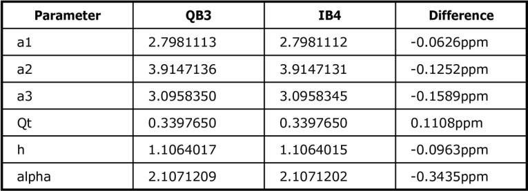
The IB4 alignment is a specific case of the QB3 alignment, when a2 = 2.5004995097549222 + √(2). In practice, a2 = 2.5005 + √(2) is an acceptable approximation with errors well below 1 parts per million (ppm), as can be seen in Table 1.
Pick any table of QB3 alignments and select the one for the specific driver Qt value that matches IB4, and you shall have the IB4 response function. This way, there is nothing special about IB4; it is just a specific instance of the QB3 alignments, but it is the specific one Thiele derived by replacing a second-order polynomial with two (identical) first-order polynomials, which places two of the poles on the real axis.
From an impulse distortion (group delay) point of view, we are only dealing with oscillations from the two poles located in the complex plane, which should give a very nice behavior in the impulse response, provided the poles are well damped (located away from the imaginary axis). The other two poles located on the real axis, are critically damped, so there is no oscillation from these terms as the (e.g., step response) signal decays.
In the above code, a proper solver is used to identify h, which is how the theory is described by Small [2]. We could instead implement a loop, by copying what was presented for the QB3 alignment [1]. The solver is what you find in the theory; the loop favors solving for several Ql values in parallel as well as portability of the code.
If you have a specific driver in mind, chances are slim that it will be able to match the required Qt-value exactly, but if you allow some computational error, one could simply ignore that the driver at hand deviates by a few percent (e.g., 5% to 10%). Note that a 5% deviation is a small one, considering measurement tolerances and the fact that all these calculations are based on a simplified model of the driver and box, and that the results may depend on, for example, the temperature of the environment. This is not an accurate science.
When Qt is not matching the IB4 case exactly and given the intimate relationship to the QB3 alignment, a simple solution is to use the QB3 alignment, where Qt may be chosen freely.
Note: Thiele studied not only Inter-Order Butterworth but also Inter-Order Chebyshev responses in his article [4].
Evaluation
From Figure 1, we can see that the Inter-Order Butterworth frequency response is extended a bit further than the LR4, but then drops off more steeply.
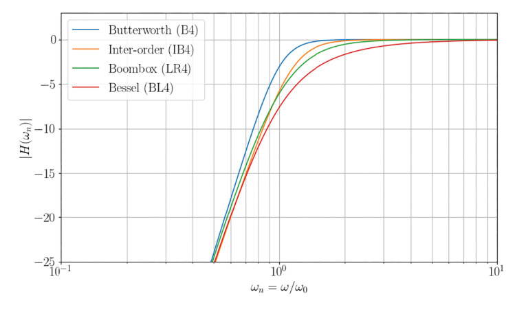
Although it might look like IB4 and LR4 cross at the -7dB point, for a specific real driver, the crossover point is a bit higher in frequency. This is due to how the normalization is based on h. For IB4 (Ql = 10) with h = 1.115, the offset in frequency relative to the driver’s free air resonance frequency is given by √(h) (i.e., 5.6%), whereas for LR4 with h = 1, there is no offset. For a specific driver, the frequency response of the two alignments crosses at about -6dB. Therefore, such a minor shift in frequency doesn’t change our overall observations or conclusions in this case, but one should be aware that normalization can lead to false observations and conclusions.
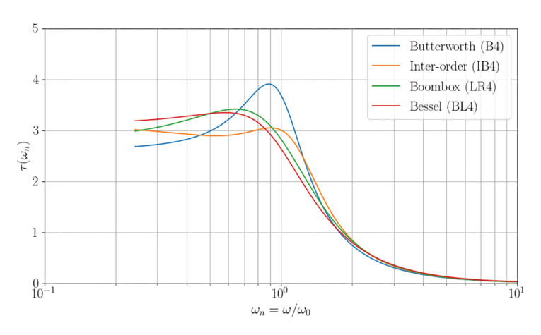
Group delay is a computation of the rate of phase change versus frequency, which essentially means it is a way to show the phase response. I prefer this view over a “raw” phase curve because group delay is a convenient measure of the linearity of the phase with respect to frequency.
It can be seen from Figure 2 that the group delay rises in a similar way to the Butterworth B4 alignment but then levels out at a nice low group delay, so we avoid the peak. It is thus to be expected that a bass reflex system tuned to the IB4 alignment will perform excellently with impulsive bass, but it is difficult to gauge if it will be better or worse than the LR4 alignment. To its disadvantage, the IB4 alignment shows a higher level of group delay and more steepness in the passband and into the roll-off, while in the stop band (with the SPL level reduced about -10dB and below), it becomes flatter and at a lower level. Flat group delay and a low level of group delay are good, but these features are in the stop band, where they are likely less audible.
A simulation with a specific driver in Speakerbench [8] indicates the step response of an IB4 alignment settles equally as fast as the LR4 (BB4) alignment. The LR4 shows higher damping. The IB4 shows another overshoot, but some balance of the responses from the two oscillators means the IB4 settles fast in the end. This could be interesting for a designer who prefers a low-damping (equivalent to low-loss) type of design. In practice, balancing two oscillators is challenging. The two oscillators in a bass reflex design are defined by: 1) the driver in the box; and 2) the port in the box, and driver parameters are not stable but change with signal level, environmental parameters, and due to aging. Nevertheless, being close to the desired target might suffice.
Summary
We have defined the IB4 alignment for lossy bass reflex designs. Allowing for some alignment error, it is fair to conclude that driver Qt in the range of 0.32 to 0.38 is feasible for the implementation of an IB4 bass reflex alignment. Studying the Scilab script, Qt is not an input parameter to any of the calculations, which means when Qt is not correct, this is simply ignored. The IB4 alignment features a surprisingly flat group delay combined with a flat extended (quasi Butterworth) frequency response. The IB4 alignment is an interesting alignment, and unfortunately it has been overlooked and neglected. One reason could be that the article by Thiele is not readily available. VC
Author Acknowledgment: Thank you to Jeff Candy, who has helped with the derivation of these algorithms as implemented into the Alignment Chart of the Speakerbench [8] web application. It was Jeff who noticed the IB4 is a specific instance of the QB3 alignments. Thank you to Mark Kravchenko for proofreading and for his help searching for a free copy of the article by Thiele [4], but without any luck finding an online source, and so I have concluded it is only available behind a paywall. VC
Appendix
This Scilab script shows how the results in Table 1 are calculated:
// ib4_qb3.sce - comparison (lossless)
kappa = sqrt(2 * (sqrt(3) - 1)); lambda = sqrt(3);
a1 = (2 + kappa) / lambda^0.25;
a2 = (1 + 2 * kappa + lambda) / sqrt(lambda);
a3 = (kappa + 2 * lambda) / lambda^0.75;
Qt = 1./sqrt(a1*a3); h = a3/a1;
alpha = a2*h - h.^2 - 1;
a2qb3 = 2.5005 + sqrt(2);
// a2qb3 = 2.5004995097549222 + sqrt(2);
a1qb3 = sqrt(2*a2qb3);
a3qb3 = (a2qb3^2 + 2)/(2 * a1qb3);
Qtqb3 = 1./sqrt(a1qb3 * a3qb3);
hqb3 = a3qb3/a1qb3;
alphaqb3 = a2qb3*hqb3 - hqb3.^2 - 1;
printf('Param - QB3 - IB4 - Diff \n');
printf(' a1 %f %f %f \n', a1qb3, a1, 1e6*(a1/a1qb3 - 1));
printf(' a2 %f %f %f \n', a2qb3, a2, 1e6*(a2/a2qb3 - 1));
printf(' a3 %f %f %f \n', a3qb3, a3, 1e6*(a3/a3qb3 - 1));
printf(' Qt %f %f %f \n', Qtqb3, Qt, 1e6*(Qt/Qtqb3 - 1));
printf(' h %f %f %f \n', hqb3, h, 1e6*(h/hqb3 - 1));
printf('alpha %f %f %f \n', alphaqb3, alpha, 1e6*(alpha/alphaqb3 - 1));
References
[1] C. Futtrup, “Computation of Bass Reflex Alignments,” Voice Coil, pp. 1 and 5-11, May 2024.
[2] R. Small, “Vented-Box Loudspeaker Systems Part IV: Appendices,” Journal of the Audio Engineering Society, Vol. 21 Issue 8, pp. 635-639; October 1973.
https://aes2.org/publications/elibrary-page/?id=1941
[3] R. M. Bullock, III, “Thiele, Small and Vented Loudspeaker Design, Part IV: Alternative Alignments,” Speaker Builder, 1981, Number 3 (July/August/September), pp. 18-27.
[4] A. Neville Thiele, “Inter-Order Response Characteristics for Simplified Active Filters,” FIREE (Proceedings of the IREE), March 1974, pp. 57-60.
[5] V. Dickason, Loudspeaker Design Cookbook. Please select any of them, from about the 3rd edition and onward. In the 8th edition you’ll find the IB4 alignment mentioned in Section 2.50 and in Table 2.10 in Section 2.60, pp. 63 and 70.
[6] R. Small, “Vented-Box Loudspeaker Systems - Part I: Small-Signal Analysis,” Journal of the Audio Engineering Society, Vol. 21 Issue 5, pp. 363-372; June 1973.
https://aes2.org/publications/elibrary-page/?id=1967
[7] C. Futtrup and J. Candy, “Parameter Estimation and Box Simulation with Speakerbench (Part 1) - Model Parameter Comparisons”, audioXpress, August 2021;
[8] Speakerbench, https://speakerbench.com simulation of the Scan-Speak 18W/4531G00, datasheet downloaded at
https://loudspeakerdatabase.com/ScanSpeak/18W-4531G00
This article was originally published in Voice Coil, July 2024