Bass reflex alignments are a vast topic with a history that fundamentally starts in 1961 when Albert Neville Thiele published his seminal articles “Loudspeakers in Vented Boxes” Part I and II. These were presented at the 1961 Institute of Radio Engineers (IRE) convention in Sydney, Australia, and later published in the proceedings.
To the best of my knowledge Thiele invented the concept of alignments in relation to loudspeakers. So, what is an “alignment?” Inspired by RF terminology, Thiele’s idea was to align a loudspeaker bass reflex vented box high-pass response with an equivalent high-pass filter function. So, the word “alignment” comes from this idea that we align the response with a filter function — the advantage being that the behavior of a filter function was well known at the time. Prior to Thiele’s idea of aligning the response with a filter function, bass reflex was designed based on good practice rule of thumb, and/or possibly an iterative process. Generally speaking, we never really knew what we were going to get.
Thiele’s idea changed all that. The way I see it, it was a stroke of genius on his part and indeed he was a genius, as his later work demonstrates. So, the purpose of this design method where we align the bass reflex response with a filter function, is to design a loudspeaker predicting what we will get in regard to frequency response, time response, and more, even before building the box.
At this stage we could ask, “OK, but what filter function should we use?”

Let’s look at the known filter functions at the time, in 1961. But first we need to mention the Chebyshev filter function, so named after Pafnuty Chebyshev. He was a Russian born in 1821 and he died in 1894, long before we were doing loudspeaker designs. But he did some of the underlying math which then came into use here.
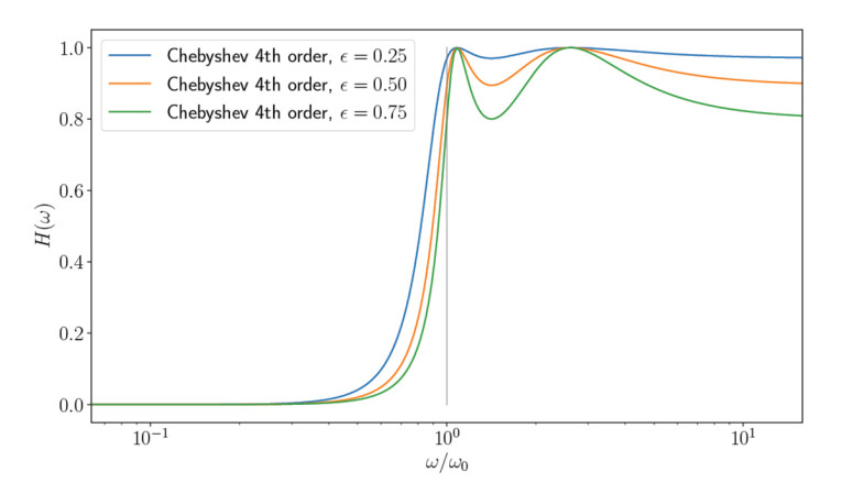
What characterizes a Chebyshev filter function or bass reflex response is that we allow the response to have some ripple. We have a response that goes down in frequency, and we allow some ripple before roll-off. And we extend that roll-off as far down in frequency as we can, while we make the ripples equal in height so overall they are minimized. And we can regulate the ripple to our desire, within limits. We can choose, for example, half a decibel ripple, which some people would say is almost unnoticeable, or one decibe. It’s up to us. Obviously, there are an infinite number of Chebyshev filters from which to choose, and in relation to loudspeakers this was first described by F. J. van Leeuwen in 1956.
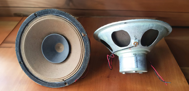
Van Leeuwen published an article that was 40 pages long. It was published in Dutch and in a scientific magazine named the Netherlands Radiogenootschap. Since I don’t read Dutch, it was very difficult for me to muddle my way through it, but he writes a lot of nice math, including how to measure the driver parameters where he uses the Philips-type 9710/M01 driver as an example.
With the high Qt of that Philips driver, he describes two types of equal ripple responses that he can obtain with this driver. He never mentions Chebyshev explicitly and he isn’t clear about aligning his bass reflex response with a filter function.
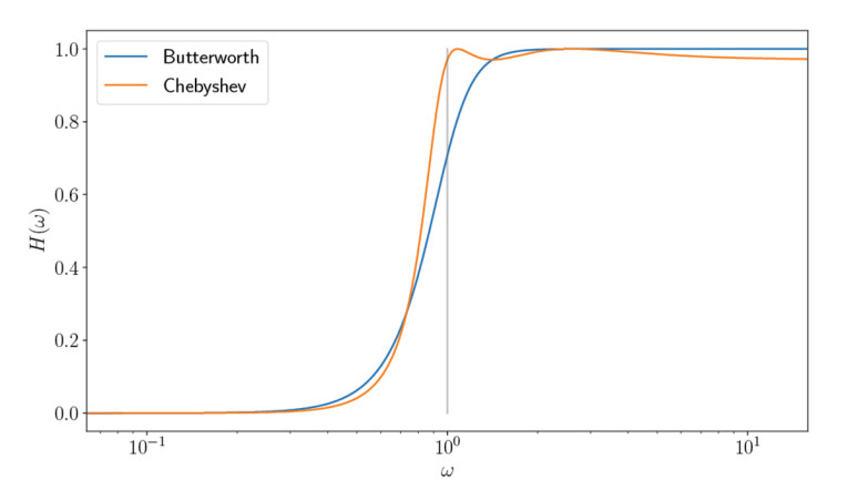
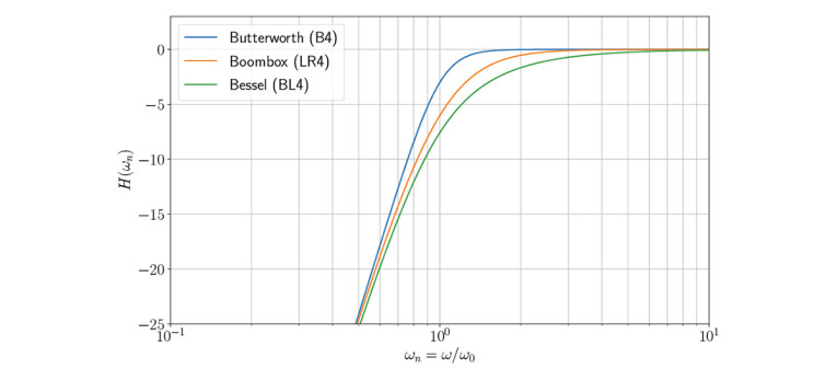
If we take this Chebyshev alignment and instead we set the ripple to zero, it becomes a maximally flat magnitude filter, which is also named the Butterworth response.
Butterworth and Bessel Filters
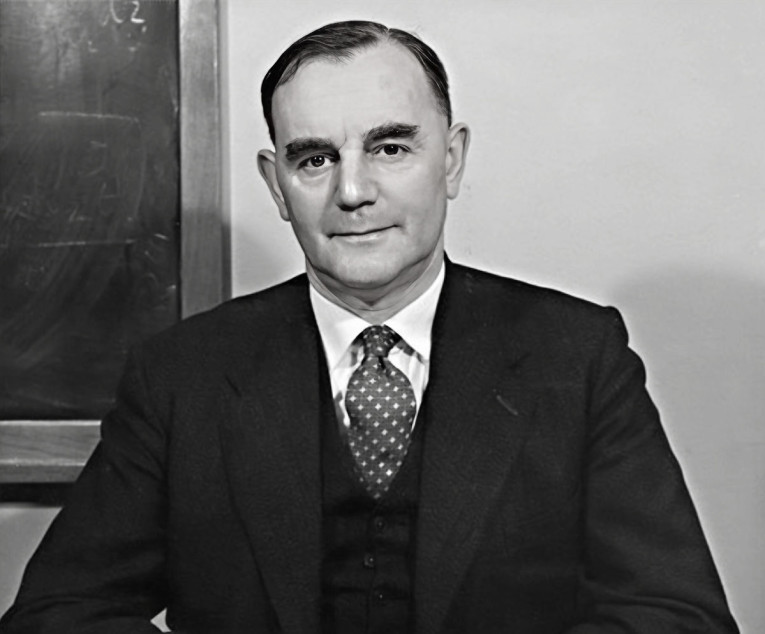
And that brings us to the next filter function: This one is named after a mathematician named Stephen Butterworth and he was born in 1885 and he died in 1958. He described his Butterworth response around 1930.
This filter offers the sharpest roll-off; the most extended bandwidth, and therefore gives us the sharpest knee point without any ripple in the passband. In relation to bass reflex loudspeakers, it’s a discrete alignment, which means we need to select a specific driver with a specific Qt value, and tune that with a specific box and port, and then we can obtain this discrete alignment.
We go from bass reflex and fourth-order responses; instead we look at a second-order filter function. The knee point Q — the roll-off — is a Q of 0.707 or 1/√2. But for a fourth-order response it is not defined as a single Q value. Although on the Internet we sometimes see the Q equal 0.707 mentioned for a fourth-order system, it’s not really like that — don’t trust everything you read on the Internet.
If these filter functions were described before loudspeaker alignments were invented, who did the work related to loudspeakers? I believe that Thiele’s article series is the first time where we see this correlation.
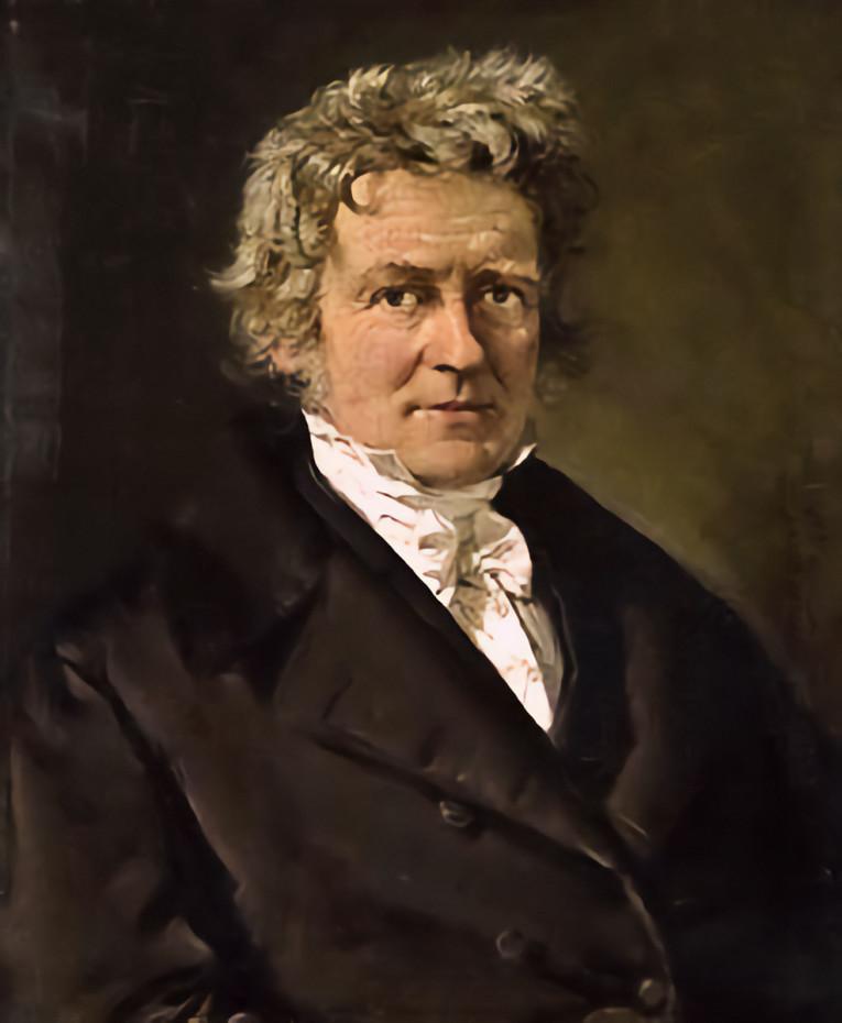
Another one is called the Bessel filter function. The Bessel filter is named after Friedrich Wilhelm Bessel, a German mathematician and physicist born in 1784, who died in 1846. Although it was already known at the time, it wasn’t mentioned by Thiele, but Bessel laid out the math that described the filters with the fastest settling time. I’m sure he didn’t have any clue about the particular application to loudspeakers, but he did a lot of nice math back in his day.
The practical application was worked out by W. E. Thomson in 1949, in a scientific article titled “Delay Networks Having Maximally Flat Frequency Characteristics,” where he described this filter function applied to delay lines.

Thomson worked at the post office research station, and he was active as late as 1977. We can imagine that when we develop a delay line, we would like it to have a flat delay, and a flat group delay — not a minimum group delay — and that’s why he used these Bessel filters, which sometimes are also called Bessel Thomson filters.
Again, second-order filters are described as having a Q value of 0.577 — so a lower Q value than a Butterworth — or we could also say 1/√3, but again for fourth-order response function the Q is not uniquely defined.
Critically Damped Filter Function
The last one I would like to mention is the Critically Damped Filter Function. The second order has a Q of 0.5, which means no overshoot in the time domain, but it suffers from very early roll-off when looking at the frequency domain. A Gaussian filter is designed to give no overshoot to a step input function, while minimizing the rise and fall time. In my opinion there is no point in going lower than a Q of 0.5, which is also 1/√4.
This is just to make it clear that there is a relationship with the square roots. Obviously 0.5 is an exact number, so we don’t need to calculate square roots to get all the decimals.
If we want to we can describe a fourth-order filter with its polynomial — we can describe it as two second-order polynomials that then can be multiplied or expanded into the fourth-order polynomial with which we’re working. Or vice versa, when we have the fourth order, we can find two second orders that describe it.
Each of these second-order filters that makes up our fourth-order response, have a Q value that we can find in the polynomial. Therefore, when we see anyone mentioning the Q value of a fourth-order response, it must be some sort of composite of those two Q values, but that’s not uniquely defined. Meaning we can’t just add them up or multiply them or anything like that... So maybe it’s better not to talk about Q values when we talk about a fourth-order response.
Let’s Talk About Bass Reflex
Albert Neville Thiele was born in 1920 and he died in 2012. He came up with this idea to align bass reflex loudspeaker response functions with equivalent filter functions. Computers were not readily available yet, so the concept of alignment was very helpful in determining our end goal. Thiele described fourth-, fifth-, and sixth-order Butterworth bass reflex responses (the higher orders required auxiliary electronic filtering), as well as Chebyshev responses with different amounts of ripple. Plus, he coined the term sub-Chebyshev alignment for lower Qt drivers, and the quasi-Butterworth’s response, or quasi-third-order Butterworth’s response, which as far as I know was a new concept at the time.
This response, named QB3, allows to tweak a box and a driver with a given port tuning to have a soft roll-off, eventually becoming a fourth order, of course, because that’s how a bass reflex works... It’s always a fourth order in the end. But it’s a soft roll-off and it has this tendency to be more like a third order.
With this concept we could choose a discrete, specific driver, box, and port tuning, or we could select from a range of drivers with some Q values, and then of course we would have to pick the right box size and port tuning. But suddenly we have the flexibility to choose from a range of drivers, or drivers with a range of Qt values, and that’s quite nice when we have a degree of flexibility with regard to the choice of the driver we want to use.
Thiele’s two-part article is so important that it was later republished in the Journal of the Audio Engineering Society in 1971, 10 years after being published for the first time.
The Bessel or Bessel Thomson alignment is also a discrete alignment, which only exists for a specific driver to a Qt around 0.3 or — this is more or less lossless but if we add a little bit of a loss — we can say 0.32 or whereabouts (in practice there’s always some losses).
Whenever a driver Qt deviates a bit from these numbers, we talk about an approximation to that alignment, which is perfectly fine if we are within 5% or so.
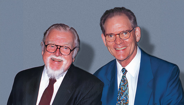
Richard H. Small
Richard H. Small is from San Diego, CA, in the US, but he went to Australia, where he got a part-time job at The University of Sydney, as a teaching assistant in the electronics lab. He wrote his PhD thesis on loudspeakers, which came out in 1972, when he stumbled on the work by Thiele [2].
Richard Small wrote articles for the Journal of the Audio Engineering Society starting in 1969 — as far as I remember and continuing with a four-part series on vented box loudspeakers in 1973. These articles created a lot of interest across the world and essentially, within a few years, loudspeaker manufacturers were documenting their drivers with Thiele-Small parameters. This allowed engineers to sketch their designs prior to buying the driver and identify which driver was most suitable for their desired target response.
Thiele did the groundwork with the idea of alignments and Small’s work put it into practical use worldwide. Thiele once visited the Scan-Speak facilities in 2009, and he told me that he had decided to publish his two seminal articles with an Australian publisher to give Australians a leading edge.
Since Thiele’s papers were largely ignored until the work by Small this didn’t work out. I also have a suspicion that the reason could be a different one. Maybe it wasn’t so clear-cut who to use to publish papers, and there were more options back in the day.
My colleague at Scan-Speak in Denmark, Knud Thorborg, confirmed that he read the articles by Thiele shortly after they were published, in 1962. Thorborg [3] once told me that they received Thiele’s original IRE articles at the Peerless Factory on Amager in Copenhagen. The engineers at Peerless were quite interested, and they tested the theory but for some reason it didn’t work out.
Thorborg speculates that the reason it didn’t work for Peerless drivers around 1962 was because they were using open weave dust caps. Meaning that air could penetrate through the dust cap, creating a lossy design. And indeed, at the time, before hi-fi, the dust caps were there just to prevent dust from entering the magnet system! Later, dust caps were sealed, and air pressure had to be relieved from between the dust cap and the pole piece underneath, which at Peerless they do by putting holes in the diaphragm. Other designers vent through the magnet system.
There could be other reasons why there were discrepancies from the theory by Thiele, but I think this is the real reason why Thiele’s work didn’t pick up from the beginning. To put it simply, the world wasn’t ready for it yet.
Fast forward to the 1970s and a third name sometimes shows up, which I would like to mention and that’s John Ernest Benson (1911-1989). He was also associated with Sydney University, and he wrote a three-part series of articles printed in 1968, 1971 and 1972, which became an entire book called Theory and Design of Loudspeaker Enclosures.
Benson was the examiner of Richard Small’s PhD thesis and Benson’s work was quite comprehensive but maybe a bit pedantic in his approach. Personally, I think it was Small’s work that presented a design method that was accepted worldwide.
Linkwitz-Riley Filter Function
In the mid-1970s Siegfrid H. Linkwitz described an electrical filter named the Linkwitz-Riley filter, named after himself and a colleague, Russ Riley. This filter function applies two second-order Butterworth responses in series, so-called cascaded filters — as described previously, taking two polynomials, each of those having a Q of 0.707, so they are Butterworth responses, and they are identical.
This article was published in February 1976, but the point to retain is that there is no bass reflex alignment named “Linkwitz-Riley.” Also, when it comes to bass reflex alignment, I would like to mention William Hoge because he described what he called the Boom Box alignment or the BB4 alignment. He also cascaded two identical second-order filters and Hoge’s description of the Boom Box alignment is from October 1976 — eight months later [4].
Hoge doesn’t work with low Qt drivers... In fact, he proposed the Boom Box for high Qt instrument speakers, and therefore this response will always have a peak before it rolls off.
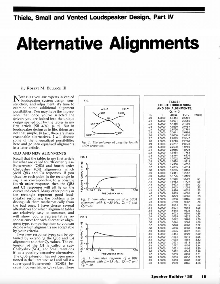
The idea to extend the Boom Box alignment for lower Qt drivers is the work of Robert M. Bullock, III and his extension is called the Sub-Boom Box or SBB4 alignment. He described it in an article published in Speaker Builder magazine [5], in 1981. In principle his reference was just to explain that good bass reflex configurations exist that are not described by classical alignments.
If we choose our parameters correctly, the Boom Box/Sub-Boom Box alignment will be the bass reflex equivalent of a Linkwitz-Riley filter. We get in that ballpark if we choose the driver Qt around 0.36, or 0.37, and it’s in a design including losses.
In similar ways, Bullock also shows the SC4 — the so-called sub-Chebyshev fourth-order, which was previously described by Thiele, as well as the super-QB3 — where “super” is not “super good” but it means that the Qt of the driver is higher than what we would choose for a B4 alignment. So, we’re above a Qt of 0.4. He extends this QB3 to drivers of a higher Q value, and it becomes this SQB3 or super-QB3. And because the Q value is like it is, it’s not linear in frequency response but it has a peak in the response.
Regarding these alignments, I once attended a practical demonstration by Ulrik Schmidt, who worked at Scan-Speak at the time (now with Danesian Audio/SB Acoustics), and while I was working at Dynaudio, around 2001. It was a presentation for the Danish Electroacoustic Fellowship (DEF) and there were many people in the room. Ulrik had designed three boxes, each made with a similar driver but tweaked for different Qt values, so that he could align them exactly with a C4 alignment, a Chebyshev alignment; the B4, which is this discrete alignment where we need a very specific Qt; and the Bessel alignment.
With this demonstration, we could clearly hear the difference in sound quality. It became immediately apparent that the C4 alignment sounds “dark” and “dull” and lacks detail, whereas the Bessel alignment has the best bass performance of the three. It doesn’t go the deepest, but it sounds the best, it’s very impulsive and musical sounding. So, thank you Ulrik for that one - it was a great demonstration!
Software and Alignments
When software became available in the 1990s and into the early 2000s, loudspeaker designer software presented us with a drop-down box where we could select available alignments for whatever driver we had in the software. Or we could choose a user-defined alternative on our own.
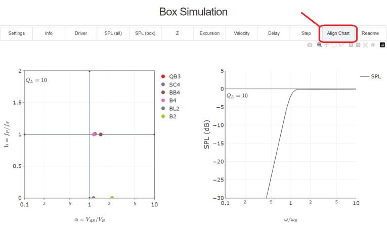
In my opinion, this user defined box wasn’t useful because I found it difficult to understand where I was with regard to alignments and to my goals. So, when Juha Hartikainen and Janne Ahonen [6] were programming WinISD — this was around 2001 maybe 2002 — I proposed they should present the available bass reflex alignment in a two-dimensional chart, instead of this drop-down box. Because in a two-dimensional chart we would then have alpha on one axis and “h” on the other — alpha is a ratio of the Vas of the driver and the box volume, and the h-value is a ratio of the port tuning frequency versus our driver’s resonance frequency in free air. I believed this would make it clear to see where we were. But they decided not to do it.
Therefore, I think Speakerbench [7,8,9,10] is the first software that gives us this 2D chart of alignments, which for me gives us an intuitive feel for where we are heading. Particularly when we do something non-conventional in the box tuning, something that doesn’t fit an exact alignment with a filter function, and we can see approximately where we are between alignments.Readers can check out the alignment chart available in the Speakerbench box simulator.
Conclusion
The concept of alignment was a major drive for speaker builders some decades ago. But with help from our personal computers, we can now calculate the results in the form of frequency response, impedance, time response, group delay, port output, air velocity in the port, and so on...
Maybe the concept of “alignment” with the filter function is no longer needed in principle. We can just look at all our graphs and see exactly how a particular box is behaving.
But, in my opinion, the concept of alignment remains useful as an anchor for what we do with the box tuning, even if the Thiele-Small as an approach is not the most accurate way to design loudspeakers, considering that we now have better loudspeaker models available.
Yet, I still think it’s a good way to have a good sense of where we are in our design. aX
References
[1] Speakerbench is a web-based application for loudspeaker design with an emphasis on an advanced transducer model. It has been available since March 2020 at speakerbench.com and requires only a web browser to use. Speakerbench simulations are more accurate than what can be accomplished with the classic Thiele-Small approach. An online manual provides complete references to the research.
[2] Voice Coil Interviews Dr. Richard H. Small, Voice Coil, 2006.
[3] K. Thorborg, Traditional and Advanced Models for the Dynamic Loudspeaker, Scan-Speak, Videbæk, Denmark, kt@scan-speak.dk
https://cfuttrup.com/Thorborg_31.pdf
[4] J. W. Hoge, “A New Set of Vented Loudspeaker Alignments,” Journal of the Audio Engineering Society (JAES) Volume 25, Issue 6 pp. 391-393; June 1977,
www.aes.org/e-lib/browse.cfm?elib=3364
[5] R. M. Bullock III, “Thiele, Small and Vented Loudspeaker Design, Part IV,” Speaker Builder, 3/1981
[6] WinISD is a freeware speaker design software for Windows,
http://www.linearteam.org
[7] Speakerbench, https://speakerbench.com
[8] J. Candy and C. Futtrup, “An Added-Mass Measurement Technique for Transducer Parameter Estimation,” Journal of the Audio Engineering Society (JAES), Volume 65, Issue 12, pp. 1005-1016; December 2017, www.aes.org/e-lib/browse.cfm?elib=19366
[9] C. Futtrup and J. Candy, “Speakerbench,” Loudspeaker Industry Sourcebook (LIS) 2020, page 124-131, www.loudspeakerindustrysourcebook.com/articles/speakerbench
[10] C. Futtrup and J. Candy, “Parameter Estimation and Box Simulation with Speakerbench (Part 1 and 2)”, audioXpress, September/October 2021.
Speakerbench YouTube Channel
The Speakerbench YouTube channel at youtube.com/@speakerbench contains videos created by engineers Claus Futtrup and Jeff Candy related to Speakerbench, a web-based application for designing and engineering loudspeakers. In addition to instructional videos on driver measurement and use of the Speakerbench web app, their videos cover educational and historical perspectives on loudspeaker design, which created the foundation for this article. Two released videos describe the principle of loudspeaker alignments as pioneered by Neville Thiele. These were widely used in the industry from the 1970s until modern computer software took over. The videos, and now this article, may be considered a tribute to Thiele for his invaluable contribution to how we design loudspeakers. Here are the direct links to the two videos:
https://youtu.be/xCVSRBdTBWM
https://youtu.be/J0wvMkreUhY
This article was originally published in audioXpress, January 2024.