A critically damped loudspeaker is a system that has no overshoot to a step function input. A critically damped second-order closed box is known from theory and implies that the box is designed such that the system Qtc = 0.5. In this fourth article in our series about the invention, concept, and historical perspective of loudspeaker bass reflex alignments, we will now describe the Critically Damped Fourth-Order (CD4) bass reflex alignment. This alignment has, as far as I’m aware, never before been discussed in literature related to loudspeaker design.
The Calculation Including Leakage Loss
In a bass reflex design, we achieve no overshoot to a step function with a fourth-order polynomial if the response has all poles on the real axis. If we limit ourselves to h = 1 (with all poles on the unit circle), this becomes a special case of the (Sub-) Boombox alignment, where the damping ratio is zeta = 1, which is equivalent to each second-order filter Q = 1/(2 zeta) = 0.5. We remind ourselves that a bass reflex system consists of two oscillators: 1) the driver in the box; and 2) the port in the box, and each of these two second-order systems must be critically damped (i.e., have a filter Q=0.5, which means they are second-order Linkwitz-Riley filter functions). Since a second-order Linkwitz-Riley filter is composed of two cascaded first-order (Butterworth) filters, you can also say the fourth-order critically damped system consists of four cascaded first-order filters. The normalized response function becomes:
G(s) =s4/(s+1)4
=s4/(s2+1/0.5*s+1)2
=s4/(s4+4*s3+6*s2+4*s+1)
Using Scilab, we may calculate the CD4 alignment as follows:
Ql=10 // sqrt(a1 * a3) = sqrt(16) = 4
Qt = 1./(4-1/Ql)
h=1
// a2*h - h^2 - 1 = 6*1 - 1^2 - 1 = 4
alpha = 4 - 1./(Ql * Qt)
Vb=Vas/alpha
fp = h * fs
Qt = 1./(4-1/Ql)
h=1
// a2*h - h^2 - 1 = 6*1 - 1^2 - 1 = 4
alpha = 4 - 1./(Ql * Qt)
Vb=Vas/alpha
fp = h * fs
where again Qt is not something you can specify yourself but is given by the equations because the CD4 alignment is a discrete alignment, like the previously discussed alignments (B4, BL4, LR4, and IB4). The provided code includes Vas and fs, but they are not defined. Either specify the values for the driver you intend to use or exclude the last two lines from the code you execute in Scilab; otherwise, Scilab will inform you these are undefined variables.
Please note that, in a reflex box, setting the driver in box Qtc = 0.5 does not provide the correct filter Q, but rather, for the lossless case, Qtc = Qt * √(alpha + 1) = 0.559. For a design with leakage loss, you may recalculate Qt and alpha. Leakage loss results in a smaller alpha and consequently a larger box, which means Qtc is reduced. To arrive at Qtc = 0.5, one must set Ql = 1.5 (Qt = 0.3). This is awfully lossy, and we conclude that, in practice, for a CD4 reflex box with a plugged (stuffed or covered) port, Qtc will always be larger than 0.5.
With h = 1, we imply that the driver’s resonant frequency and the port tuning coincide. With Ql = 10, the required Qt value is 0.2564, and in the lossless case, we get driver Qt = 0.25. Remember to compensate for all electrical resistance in series with the driver. The CD4 alignment is a special case of the (S)BB4 alignments, similar to LR4, but in this case targeting no overshoot in the time domain. Therefore, the equations are similar, and it is a one-parameter alignment, but with our requirement of being critically damped and consequently having all four poles on the real axis (at -1), it follows that the calculation of the required Qt and alpha are a bit different.
Evaluation
It can be seen from Figure 1 and Figure 2 that we sacrifice bass output since the low-frequency roll-off is softer than even a Bessel BL4 alignment (significantly). This alignment will also have the lowest possible group delay in the roll-off from wn = 1 and up to about 1.8, and it is lower than for the Butterworth and Bessel alignments down to the frequency response roll-off point and -25dB into the stopband.
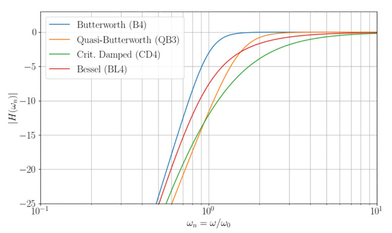
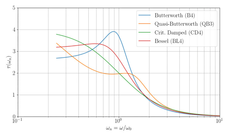
It may seem a bit unfair to compare CD4 with B4 and BL4, since these require different driver Qt values. Hence, the lossless QB3 alignment with a driver Qt = 0.25 is plotted for a 1:1 comparison. It can be seen from the frequency response graph that CD4 has the least bass output of any of the plotted alignments.
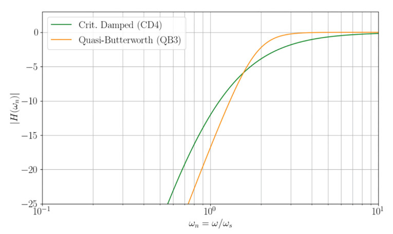
With leakage loss Ql = 10, the QB3 alignment h = 1.494 (i.e., the port tuning frequency is significantly higher than for the CD4 alignment with h = 1), and QB3 alpha = 4.385 (compared to 3.6 for the CD4 alignment), such that the QB3 box is approximately 20% smaller in volume. The normalized graph can be misleading when comparing alignments with different h values. The cause is the normalization w0 = √(wp * ws) = ws * √(h).
In Figure 3, we plot CD4 and QB3 with a different normalization, now relative to the driver’s free air resonance frequency, ws. This means a given driver with the required Qt value could be chosen, the two alignments are simulated, and a 1:1 comparison is possible.
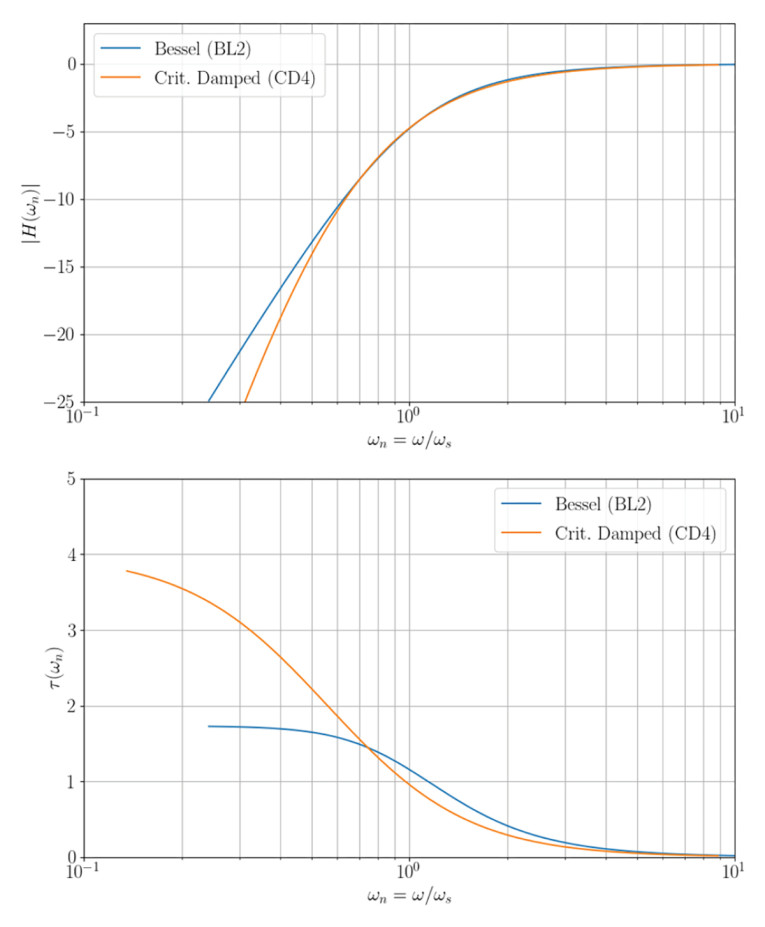
In Figure 4, the CD4 alignment has an ever-slightly softer roll-off than a closed-box BL2 alignment (Qtc = 0.577) and also less group delay in the roll-off area, crossing when the frequency response is down to about -8dB. Compared with a closed box with a higher box-Q, the improvement in group delay with the CD4 alignment is more significant, but the closed-box alignment will also have a flatter frequency response. In the stopband, a bass reflex alignment due to the fourth-order response function will always have more group delay.
From Figure 4, we can conclude that, whereas the QB3 alignment can provide something that resembles a third-order response in the roll-off region, the CD4 alignment actually shows a low-Q (soft knee) second-order response in the roll-off region.
We have defined the CD4 alignment for lossy bass reflex designs. Allowing for some alignment error, it is fair to conclude that driver Qt in the range of 0.23 to 0.28 is feasible for the implementation of a CD4 bass reflex alignment. The proposed Critically Damped Fourth-Order alignment gives us the maximum output level with the desired time domain properties of no overshoot in the response to a step function input, and as such, it is the best we can do with our polynomial response function within these constraints.
We can conclude that it makes little sense to utilize a driver with a Qt value lower than about 0.25 in a bass reflex design because a lower Qt will sacrifice the low-frequency roll-off even more without gaining a better time response characteristic because we already have a critically damped response, but it is mathematically possible and you will end up with a smaller box volume, and the time response will settle faster due to the earlier roll-off (loss of output level). This way, we can think of the CD4 alignment as a practical lower limit case for SBB4 alignments.
When would it make sense to apply a CD4 alignment? One application could be a subwoofer with the system tuning at a very low frequency (e.g., 16Hz), in which case one would not notice the lack of bass with most music, and the reduced bass at lower frequencies is possibly compensated by room gain. With the proposed 16Hz system resonance frequency, the free field -3dB point is at 40Hz, just as an example.
Another use case could be a design with two woofers of different sizes, with the smaller being more of a mid-bass driver aligned with the CD4 alignment, whereas the larger driver fills up with the additional desired bass at lower frequencies. One could also imagine CD4 used with a midrange in a bass reflex enclosure, then without a passive high-pass crossover, where the midrange can have a powerful motor system and accordingly high efficiency (and low Qt), either with a high nominal impedance or in an active system, but it isn’t investigated here how to integrate such a roll-off with a woofer with a low-pass crossover.
No matter what, the roll-off characteristic requires some attention, possibly electronic EQ (a bass boost). This might explain why a CD4 type of alignment isn’t commonly discussed for bass reflex designs. VC
Author Acknowledgment: Thank you to Jeff Candy, who has helped with the derivation of these algorithms as implemented into the Alignment Chart of the Speakerbench, https://speakerbench.com
This article was originally published in Voice Coil, August 2024