Several years ago I was lucky to be in a private suite at a trade show where Analog Devices, Inc. (ADI) was showing off its new IC to send up to 32 bidirectional digital audio signals, along with control, over a simple twisted pair of cable to and from multiple boards.
Having a year prior tried to solve a customer application for a consumer product that could send half a dozen audio channels plus control in just one direction between two devices over a low-cost cable and a connector, the benefit of a low-cost chip that could handle more channels and up to
11 nodes to distribute the audio to/from had obvious value. I wanted it!
It was quickly pointed out that these new wonder chips were only for automotive use and no amount of histrionics would get me access.
Fast forward a few years to the fall of 2019. ADI announces that the Automotive Audio Bus (or A2B, which are registered trademarkw of Analog Devices, Inc.) parts and tools would become regularly available through distribution. The audio business had changed in the intervening years, but there are still plenty of applications where A2B solves problems that don’t have good alternatives. The name A2B still reflects the automotive roots of the product, but I like to think of it meaning “send audio from A to B, and C, D, E, etc.”
Digital Audio Interfaces for ICs
Analog-to-digital converters (ADCs) and digital-to-analog converters (DACs) for audio applications all have I2S interfaces, which like the well-known I2C specification was created by Philips [1]. In its basic form, I2S sends pulse-code modulation (PCM) data and clock over three wires: Data, bit clock (used to clock the data), and word clock (indicates the start of a new PCM packet, also called frame sync). Many devices also need a master clock signal that is a multiple of the word clock frequency, typically 128× or 256×. The data field for each PCM sample is typically 16 bits or 24 bits in length, but most devices use a 32-bit field size; the data is aligned MSB first so unused bits don’t affect the value.
Figure 1 illustrates the basic timing relationship for I2S signals. Normally, the sending end places data out on the falling edge of the clock (BCLK) and the receiving end clocks it in on the rising edge. The frame sync (FS) is shifted one bit position from where you might expect it to be at the start. Most parts have the ability to control which clock edges are used, whether the extra FS bit shift is used, and if the frame sync is a pulse or 50% duty cycle, and polarity of signals.
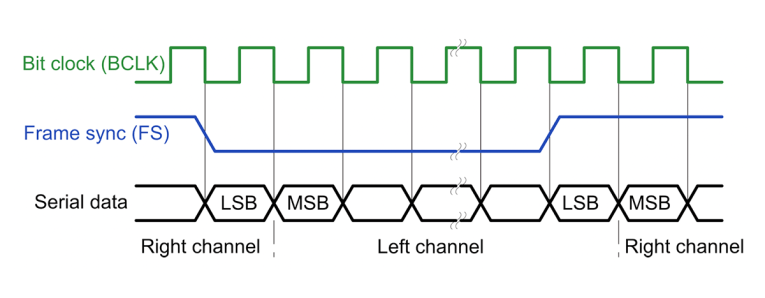
For typical 48 kHz sampled stereo audio data used in consumer devices, the frame sync frequency Fs is 48 kHz and the bit clock is 64 times that (two channels at 32 bits) or 3.072 MHz. A master clock of 256 x Fs would be 12.288 MHz. A 96 kHz sample rate would double those numbers.
The original I2S specification was for two channels, applications needing more channels needed multiple data lines. Over time the I2S concept was expanded to TDM I2S, where 4, 8, or more channels of PCM audio data are sent in a frame [2]. In the 1980s and 1990s, as was the case with I2C, other semiconductor companies developed I2S equivalent systems due to Philips’ licensing policy. I2S is now generally used for audio data converters—there are other standards for high-speed RF and industrial converters.
AC97 was a popular (used in practically all computers in the late 1990s and early 2000s) TDM approach released by Intel [3]. It combined multiple data channels and control/status over the interface. There were similar schemes from ADC/DAC manufacturers that pre-dated AC97, and AC97 itself has been replaced by newer computer-centric audio interface standards.
All of these systems for digital audio were intended for use only on a single PCB. Sending the signals over even short pieces of ribbon cable could be problematic for both signal integrity and electromagnetic interference (EMI) reasons. The odd harmonics of the clocks radiate well at the lengths of trace and cable typically encountered in bigger systems. Modulation of clock edges by the data or other signals created timing jitter that early ADC and DACs were susceptible to, degrading their performance.
PDM Interface
With the advent of voice input, it is common for products to have several microphones. In automotive cabins where voice input and Acoustic Noise Cancellation (ANC) is needed, there can be a dozen or more microphones. Traditional analog interfaces would have a number of cost and performance downsides.
For digital microphones, Pulse Density Modulation (PDM) has become a common interface format as it is easy to implement in a microelectromechanical system (MEMS) microphone design. The A2B transceiver parts include the ability for I2S or PDM input. In the case of PDM, four microphones can be directly attached and the A2B transceiver converts the PDM to PCM.
PDM requires only two wires, a clock input (usually 64 Fs), and a single data line shared by two microphones. Double Data Rate clocking is used (i.e., one mic uses the rising edge/high period and the other uses the falling edge/low period). (For more information about PDM and MEMS microphones see the Resources section.)
Why A2B?
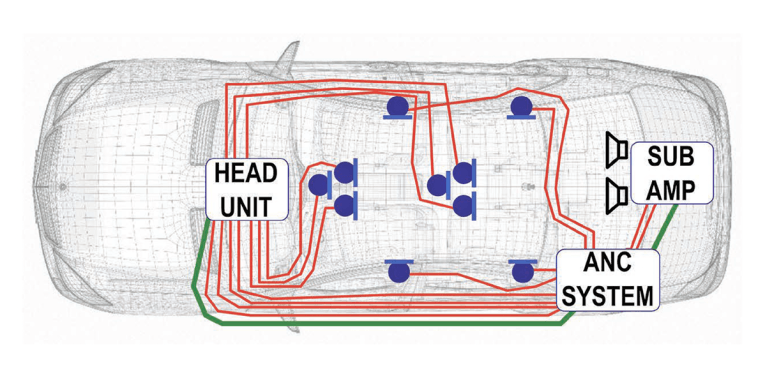
The transportation industry is driven by cost, both for building product and operational cost in terms of fuel efficiency and reliability. Electronics use in vehicles continues to rise and a traditional approach of adding more wires for each new system would be a failure, as illustrated in Figure 2. Over the years a number of automotive buses have been created, Controller Area Network (CAN) and Media Oriented System Transport (MOST) being perhaps the better known of the multitude of choices. None of the available offerings have the characteristics needed for in-cabin audio, particularly for hands-free microphone and road noise cancelation. Adding more speakers for better sound field control also adds to the wiring complexity.
It would be much simpler if, instead of home-running wires from each audio device, we multiplex them on to a single wire pair. The system can then look more like the diagram shown in Figure 3.
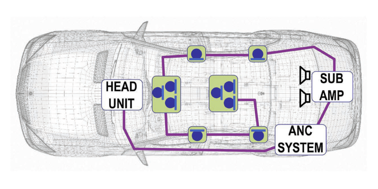
We would like the system to have multiple drops, and for low power things such as microphones, phantom power would eliminate the need to run power cables to devices. Data will need to travel in both directions over the cable. The ability to interface with device nodes that have peripherals with I2C or GPIO control means we can eliminate local microprocessors. To be useful for active noise control, very short latency — a few audio samples at most — is needed.
As might be expected from the article title, A2B can do all of that and more. A2B does not replace the other types of network protocols in use in transport, industry, or consumer applications. Instead it complements them by removing the need to transport a lot of low-latency data that those other choices were not designed to support.
AES-67 or Dante-based Ethernet networks are great for large amounts of audio between multiple boxes over long distances. MIPI Soundwire, in the other end of the data transport application space as a “talk to the chip next door” method, to-date has no announced standard interface parts for audio. FPD-Link is point to point and unidirectional data, but can go over cables.
A2B can go 15 meters between nodes and up to 40 meters total length. In many applications, the entire A2B network of devices can be loaded up from the host processor over I2C at startup and no further interaction from the host is needed. It acts like a hardware “virtual I2S, I2C, and GPIO over distance” system. There’s no software license or royalties. The per node bill of materials (BOM) parts cost is less than $8 in volume. Ethernet audio solutions can cost two times to three times more per node and have high latency.
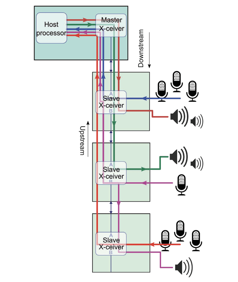
Basic A2B System
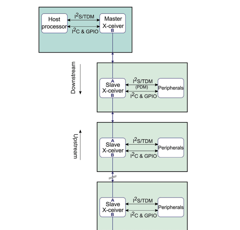
Figure 4 illustrates a basic A2B system. The A2B master node sends data downstream to slave nodes and receives upstream data. Audio data does not need to go through from master to slave or vice-versa, it can also flow directly between slave nodes in either direction. Data going to more than one node only needs to be sent once (i.e., one node can broadcast audio to all nodes or subset of nodes).
A2B moves data in packets, the packet rate is either 44.1 kHz or 48 kHz, which is normally the same as the sample rate. The system can support 2× and 4× sample rates of 96 kHz and 192 kHz. The rest of this article will be based on 48 kHz. Audio data size can be 16 bits or 24 bits. Since data is always sent at full level (i.e., end output volume would normally be controlled locally at a node), 16 bits will exceed the available dynamic range of the source and output in many cases.
The A2B bus time division multiplexes data streams into a downstream packet and an upstream packet. Starting at the master node the downstream packet is sent through each slave node — each slave mode copies off the data it needs and/or adds new data destined for a downstream slave node. When the master node’s packet hits the last node in the system, a new upstream packet is created, and each slave node adds its data and/or reads any data it needs locally. Once the Upstream packet is received at the master, the cycle repeats at the next sample start. If not all data packet slots are used, the bus is idled until the start of the next frame (sample rate) period, reducing power consumption.
For any given node, there is a maximum of 32 streams in the downstream direction and another 32 streams in upstream direction. There is an aggregate limit at each node for the total number of streams, independent of direction. For 16-bit data this is 51 streams. For 24-bit data, this limit is 34 streams.
This per node limit is not the same as the total number of unique audio streams that can exist in the entire A2B system. For example, data sent between two adjacent nodes doesn’t add to the stream count of other nodes that are up or downstream from the two nodes exchanging data.
In an A2B system with all of the processing in the master node, all data would route to and from the master node, and the 34 stream total applies. Placing the processing in the middle of the network could effectively double the bandwidth across the entire A2B network, though a master node is still needed to manage the set up. Luckily, the ADI design software Sigma Studio makes it straightforward to create these complex scenarios and off-the-shelf evaluation hardware can be used to validate the needed routing for when the routing can be defined as a set of predefined static routes. Dynamically changing routing is a more complex undertaking, and it’s worth mentioning that the system will pause briefly (the time to write out new routing tables to each node, less than 500 msec) under that specific scenario.
Not shown in detail is the I2C routing between the master node and peripheral nodes. From the master node’s host processor perspective all I2C peripherals on any node are reachable through an I2C address muxing system. The A2B transceiver parts also have GPIO and the system supports a virtualized GPIO. By using the broadcast capabilities of the A2B bus GPIO across multiple nodes can be updated synchronously. For nodes with local processing, there are also mailbox registers that the local processor can read via I2C on the local node.
A2B Latency
One of the key features of A2B is the fixed latency for audio data regardless of which node it originates on and how many nodes it is routed to. While we described A2B as packet-based, the contents of the packet are not stored and forwarded at each node. Each node starts outputting its incoming datastream within a few A2B bit periods (one A2B bit period is about 20 nsec).
Though not entirely correct, as empty slots are not sent and data packets in a given direction are contiguous, we can think of a simplified system with 16 downstream and 16 upstream slots (see Figure 5). Combined we call this the superframe, which also includes I2C data, GPIO, and other status and control bits. The master node starts by sending a packet of 16 channels (plus control) downstream. The first node grabs the data it’s been programmed to output while at the same time passing the bit stream on to the next node. This process repeats until the last node is reached.
If a particular node is the last one that needs a given audio data stream than that stream is not passed on. If the master isn’t sending (in this example) all 16 possible streams then an intermediate node can send data downstream to another node in one of the unused stream slots.
The last node, after receiving the last downstream packet, repeats the same process in the upstream direction. Intermediate nodes can read streams, stop passing ones no longer needed upstream, and add their own data destined for upstream nodes.
The entire data movement completes in one audio sample period. There’s also a sample period to clock the data in via I2S before it can be transmitted, meaning that output of I2S data can start two sample periods (nominal, there’s a small additional fixed delay) from when it was received. At 48 kHz sample rate, this totals to about 50 µsec.
The data exchange is illustrated in more detail in Figure 6, showing data being sent both downstream and upstream and how from input to output is just a little over two audio sample periods.
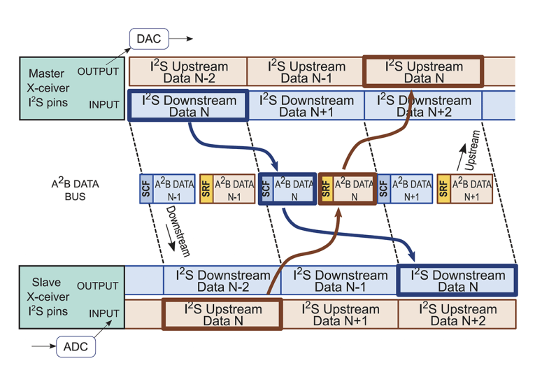
The superframe period (20.83 µsec, corresponding to 48 kHz) is divided in to 1024 bit times, for a data rate of 49.152 million bits per second (Mbps). For the remainder of the article sections, we’ll round this off to 50 Mbps.
In addition to audio data, there are headers with addressing information, CRC and parity bits to detect errors, I2C and GPIO data. Corrupted audio samples are handled by the same style of algorithms used in CD players. Even an outrageously high 1% loss is barely detectable. A2B transceivers support built in loopback and Bit Error Rate (BER) testing. It has been the author’s and others experience that bit errors just don’t happen in normal use, but it’s reassuring to know that if your car gets hit by lightning, the music will still sound great.
Summary
In Part 1, we have looked at the properties for a locally networked audio transport that has very low and deterministic latency. Basic digital audio interfaces (I2S and PDM) were reviewed.
The next part of this article will look in more detail at what’s happening on the wire pair that A2B uses to transport data and power around a system. Features designed for automotive use: excellent EMI/EMC characteristics, robustness to faults, and diagnostics, can help in designing systems that operate reliably and minimize downtime. aX
References
[1] Philips Semiconductors, I2S bus specification, February 1986 and revised June 1996.
[2] Cirrus Logic AN301, Revision 1, “Time Division Multiplexed Audio Interface: A Tutorial,” September 2006.
[3] Intel, Audio Codec 1997, Revision 2.3. April, 2002.
Resources
Analog Devices, Inc., A2B information,
www.analog.com/en/applications/technology/a2b-audio-bus.html
“PDM and MEMS microphones,” Analog Devices, Inc. Technical Article MS-2472,
www.analog.com.
This article was originally published in audioXpress, October 2020.
Go here to read Part 2 of this article series
Go here to read Part 3 of this article series
Go here to read Part 4 of this article series
 About the Author
Brewster LaMacchia started in signal processing working on military satellite communications systems. Since then he has worked on a wide range of signal processing systems, including a number of years on video processing and surround sound audio for consumer home theaters. Recently, he started Clockworks Signal Processing to develop open-source hardware for multichannel signal processing. He also dedicates time to public astronomy events to expose people to science and critical thinking. In the past 10 years, he’s helped more than 7,000 people look through a telescope for the first time.