Designing and Building Systems
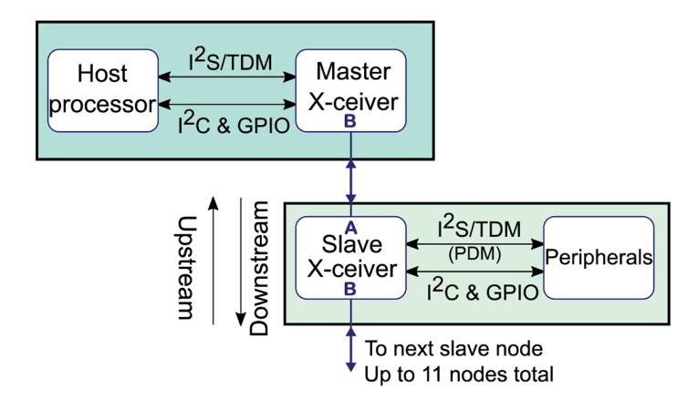
All A2B systems consist of a root (A2B master) node at the head of the single twisted pair A2B daisy chain with one or more client (A2B slave) nodes as illustrated by Figure 1. There is an overall limit of 11 nodes with up to 15m of cable between them and a 40m total system cable length.
The decision for a host processor choice is not driven by the needs of A2B control, even a small microcontroller would be fast enough to load the network configuration over I2C and manage status and control when it’s operating — mostly because I2C just isn’t that fast at 400kbits per second. That speed makes for a practical limit on how fast commands can be sent.
This I2C limit is a consideration for the node design. If the peripherals are all chatty over I2C, you’ll quickly run out of I2C bandwidth on the link between the master node transceiver and the host processor. If there are local processors on slave nodes, it is likewise best to have them boot from local flash as downloading code at startup to every slave node with a local processor would slow the startup time. A2B has a provision for holding each node’s local configuration in a small EEPROM to further reduce startup time. It’s possible to have a local processor configure the slave node from the local side as well as the transceiver supports multimaster I2C operation.
Most likely, the host processor has plenty of compute resources and the additional needs of the A2B bus control will be minor relative to the other processor tasks. What will require consideration in a host is the nature of the audio data and what type of processing must be performed on it.
This may lead to two processors on the host — one that runs general system control tasks and the other optimized for the typical DSP processing associated with audio applications that need more than a channel or two of audio. The DSP algorithms may be performed in a general processor core with DSP-like extensions, in a DSP core, or in a FPGA device. The details of that decision are driven by considerations outside of the A2B bus. The only thing to include criteria wise is that the device that is intended to process the audio have I2S ports with TDM modes that support the bit depth, channel count, and sample rates that are required.
If the system is performing active noise cancellation (ANC) or similar tasks that require low latency from input to output, then the device’s I2S ports and processing design should provide very low latency — a dozen samples at most is typical of many of these applications. This is where the low latency of A2B can really be an advantage as its two-sample latency gives leeway to the host maybe not being the fastest tool in the shed.
Client/Slave Nodes and Peripherals
The flexibility of A2B offers system designers a huge range of design choices. For example, the node could have a small DSP (i.e., ADI’s SigmaDSP) or powerful FPGAs to perform local pre and/or post processing of audio streams.
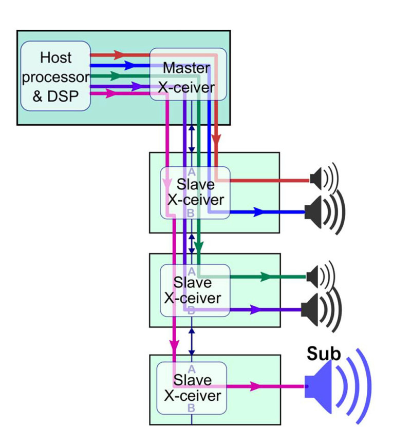
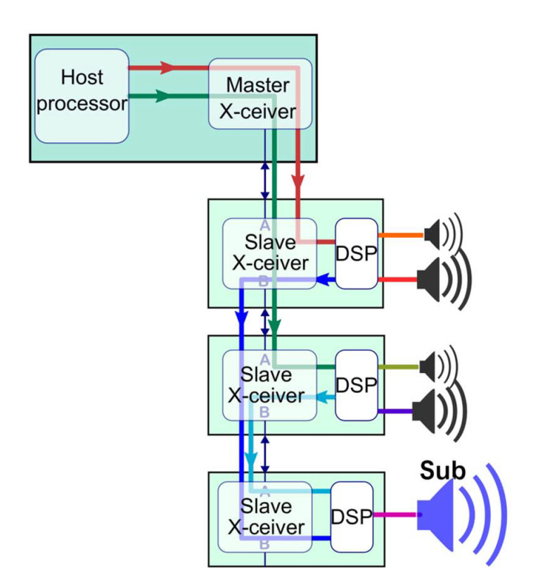
A common audio speaker configuration is a stereo two-way (mid, tweeter) speaker with a common subwoofer. We could perform the crossovers on the host node and use five A2B slots for data movement as shown in Figure 2. If we want to allow more speakers to be added — let’s say to create a basic 5.1 surround system — we’ll use more A2B channels, and now the host needs to ship with enough DSP resources to handle the worst case system. Alternately, as illustrated by Figure 3, we could use one A2B slot per speaker channel and let the local node implement the crossover and handle other local speaker equalization tasks. Non-full-range speakers would send low-frequency content to the subwoofer node, and we can easily add more subwoofers to improve performance there too.
From this basic concept, we could add features like voice input, or a Bluetooth receiver, or even an analog input for legacy source in to add-on units or even right in to the speaker box.
With flexibility comes the risk of featuritis. Creating prototypes and getting user and customer feedback before embarking on a full design effort would be critical for development of a successful product. Counterbalancing that is the time and cost to develop those prototypes. This is where ADI and its third-party ecosystem can help by allowing creation of bench demos in a few hours and integration in to end user form factor systems for evaluation in a short time period — weeks, not months.
Host/Master Node
There are a number of boards available for evaluation and prototyping. The choice will be influenced by the project’s requirements as well as familiarity with the vendor and the general software tools. In addition to the boards described in this article’s supplementary material, any suitable processor board with I2C, GPIO, and I2S can have A2B Frankensteined on to it with an A2B breakout module.
A host node has two primary responsibilities; setting up the network and providing the clock that defines the audio sample timing. All nodes’ I2S clocks are synchronized to the master node’s clock source.
To use ADI’s SigmaStudio tool for A2B development ADI’s USBi emulator module is used. It provides a USB connection for the development PC and connects to the host’s I2C bus as shown in Figure 4. USBi interfaces boards are available from ADI as well as several third-party board vendors and can be used for any SigmaStudio target.
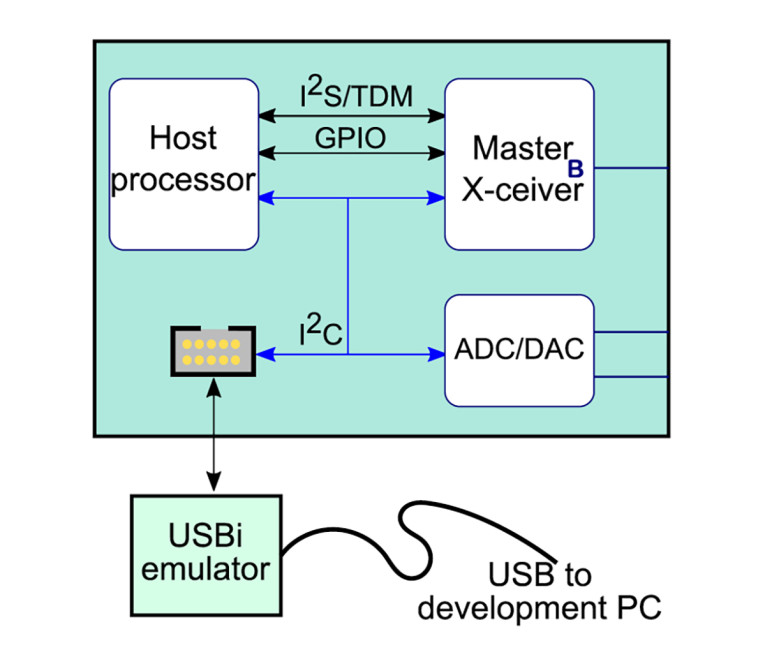
The USBi operates as an I2C bus master to program the A2B transceiver. During development, the host would skip that portion of code as well as not try and master the I2C bus when the USBi is being used. Host boards with ADI’s SigmaDSP chips on them can be programmed through the same USBi interface.
Client/Slave Node
Most of the available host/master boards can also function as A2B client (slave) nodes. Slave nodes may be locally powered or phantom (bus) powered. An important consideration is phantom powered slave boards cannot be easily probed with an oscilloscope because their local ground node is not the same as the system ground (see Part 2 of this article series) unless the audio I/O portion is galvanically isolated from the A2B portion. One workaround is capacitively coupling the analog I/O grounds. The supplementary material details available A2B client (slave) nodes in depth.
Building an Example Application
ADI’s SigmaStudio software tool will be used to build the application pictured in Figure 3, where the speaker crossover is in each node. This simple example could be expanded further by adding things such as multiband EQ to equalize the speaker’s response, or soft limiting to avoid excess driver distortion at high SPL levels, and so forth.
For the local processing, we need two different DSP applications, one for the small speakers and the other for the subwoofer. The speaker processing is a three-way crossover where we output the mid-range and tweeter locally and the bass is sent over A2B to the common subwoofer (Figure 5). Additional level controls are added to simplify system balance when different speakers might be used.
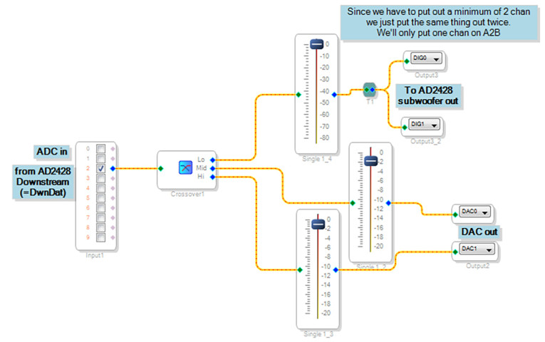
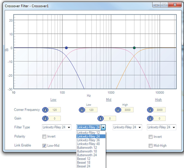
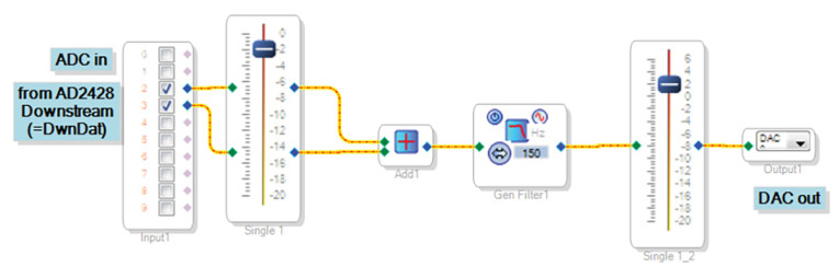
There are a number of options for crossovers and speaker EQ in SigmaStudio, including self-tuning options. Keeping this example simple, a basic three-way crossover will be used. Its settings are shown in Figure 6. We’ll overlook details of actually setting the crossover as that topic alone could fill several articles. The subwoofer node’s processing is illustrated by Figure 7.
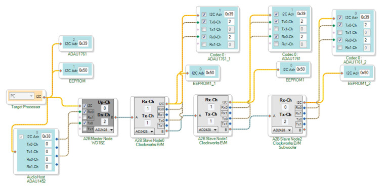
Next the A2B schematic is created (Figure 8). It consists of one master node and three slave nodes. One immediate thing that can be noticed is that the peripherals all have the same I2C address on each node. There is an I2C mux facility built in to the A2B I2C subsystem for uniquely addressing each node, eliminating most of the traditional headaches of I2C address conflicts.
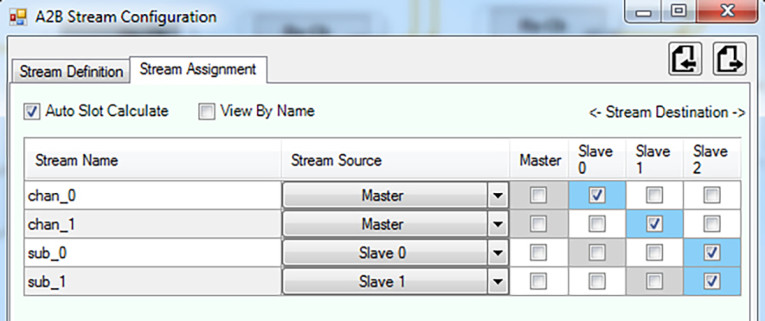
The last part of the setup is to define streams for the audio that is to be routed and then indicate which node produces the stream and which node(s) consume the stream (Figure 9 and Figure 10).

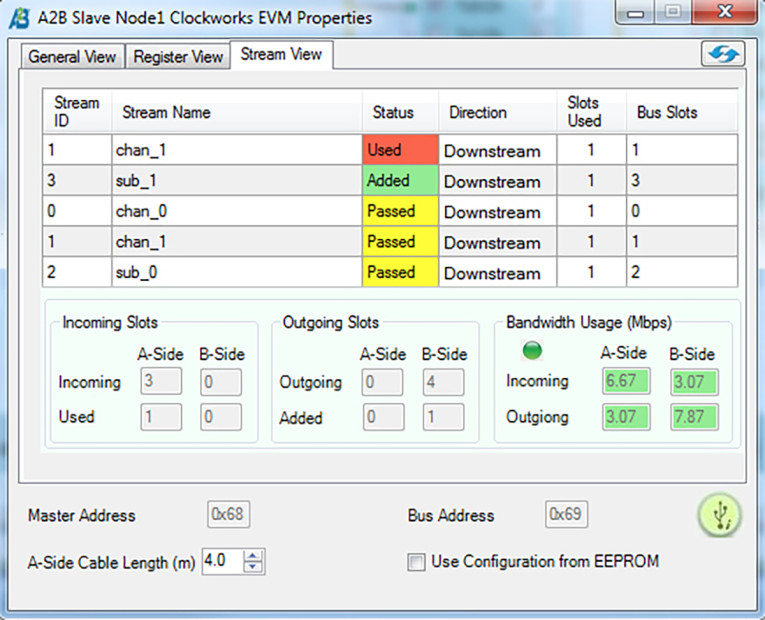
SigmaStudio can also look at the node’s properties to set the AD2428’s characteristics through either user friendly settings or raw register bits. For example, in Figure 11, we can see the audio stream activity for the second speaker node.
This example illustrates the basics of A2B configuration but overlooks some of the more complex issues that will be present in real-world systems. For example, the A2B schematic defines specific electrical positions in the daisy chain for each function (L, R, and subwoofer). What if the subwoofer was to be placed close to the master node (i.e., first in the daisy chain)?
Each node can configure its AD2428 and the DSP locally. We can assign unique IDs to each node, and could encode in that ID the type of node (speaker or subwoofer in this example). Neither of these help with the data routing over A2B, as A2B is not a network like Ethernet where nodes are defined by an address vs. physical position.
If there are a limited number of configurations then it’s possible to create diagrams for each and determine at runtime which to use. If all nodes route all data to and from the host, then the host can directly manipulate routing.
Beyond that it becomes necessary to use ADI’s A2B software stack along with custom software to dynamically manage the A2B network. Available as a C library for adaptation in to whatever environment the host processor uses, the A2B stack also allows sophisticated fault and error handling versus the simplified load-and-run approach when working exclusively with a SigmaStudio design flow.
Summary
The first three article parts looked at the underpinnings of A2B technology and the electrical design of the A2B interface. This last part of the A2B article series provided details on creating actual products around Analog Device’s A2B technology. Due to space limitations, the detailed review of available hardware for development has been placed on the Supplementary Material section of the audioXpress website.
There are many features and capabilities that this article series skipped over. Now when faced with an audio distribution problem, you’ll have enough understanding to know if A2B should receive further investigation as a solution to your design problem. There’s nothing like getting a couple of boards and experimenting. aX
Click here for Part 1 of this article series
Click here for Part 2 of this article series
Click here for Part 3 of this article series
Project Files
To download additional material and files, visit audioXpress Supplementary Material
Resources
A2B and Automotive Audio Bus are a registered trademark of Analog Devices, Inc. ADI’s main A2B webpage provides links to part information, ADI tools, and design information. www.analog.com/en/applications/technology/a2b-audio-bus.html
This article was originally published in audioXpress, January 2021.
 About the Author
Brewster LaMacchia started in signal processing working on military satellite communications systems. Since then he has worked on a wide range of signal processing systems, including a number of years on video processing and surround sound audio for consumer home theaters. Recently, he started Clockworks Signal Processing to develop open-source hardware for multichannel signal processing. He also dedicates time to public astronomy events to expose people to science and critical thinking. In the past 10 years, he’s helped more than 7,000 people look through a telescope for the first time.