For applications where the nodes will be AC (line) powered or have common connections from shielding, there are considerations for grounding that can be different from automotive applications and understanding that difference is important for system design.
Phantom Power
Before looking at the electrical interface for A2B data, we’ll review how A2B phantom power works as it’s different from phantom power systems with which audio engineers may be familiar [1]. We’ll look at two common analog systems for phantom power to help understand where A2B is different and what issues that could lead to in your own designs, particularly for non-automotive use cases.
The simplest phantom power circuit is found on PCs and similar low-end applications that use an electret-type microphone that includes a junction field-effect transistor (JFET) in a common source configuration. In this design, half the amplifier (the drain resistor) is in the equipment that the microphone plugs into, as shown in Figure 1. The coupling capacitor blocks DC. Typical values for Rx are 2.2 kΩ and 5 V for the supply. There are several variations on this basic design—some using a mini-phone TRS jack to split the power from the signal connection.
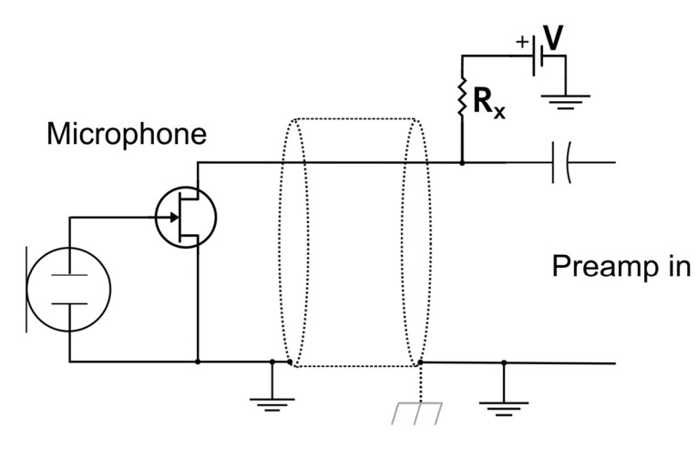
In a single-ended system, the questions of grounding and shielding exist, particularly if there’s no metallic chassis to connect the shield to. As drawn in Figure 1, the shield is being used as the return, which is typical but not desirable.
More familiar to many readers is the 48 V phantom power standardized by IEC 61938 [1]. Figure 2 illustrates the basic concept of phantom power supplied over balanced lines. The positive voltage is applied to both the positive (+) and negative (–) signals, the supply return current is carried by the ground wire. Since the two sides are matched, the common mode noise rejection of the input device’s transformer removes power supply noise.
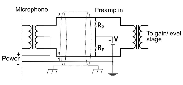
The two resistors RP, which are 6.8 kΩ, need to be well matched to maintain the overall common mode noise rejection, along with the output transformer on the microphone side having matched halves. The two supply currents cancel in the microphone transformer, as otherwise the core would have a DC bias and increased distortion.
Figure 2 was drawn with the requirements of AES-48 [2] included, which means the shield is used to connect directly to the chassis ground and the “signal” ground functions as the supply return path. Not shown is the connection between the chassis and signal ground.
Understanding Figure 1 and Figure 2 will aid in the discussion in the next section on how A2B phantom power works and how it can and cannot be used in certain applications.
A2B Phantom Power
Having been refreshed on phantom power and grounding issues with analog audio, we’ll look at the unique aspects of A2B’s phantom power design. The A2B master node can supply 300 mA, which at typical A2B voltages of 5 V to 8 V is enough power for operating a microphone or even a small DSP with ADC and DAC. As with all things that seem too good to be true, this may not be as helpful as it first seems.
A2B systems are designed to be rugged—it’s very expensive to have your vehicle serviced. Cable opens, shorts to ground or battery (24 V in some vehicle systems) must not release the magic smoke from the ICs. Having the system indicate where the failure occurred is important to keep costs down as ripping apart an entire cabin to find a failed connector after the vehicle was purchased is not going to make a good customer impression.
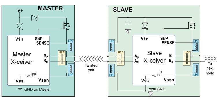
The A2B features that are helpful for automotive applications must be accounted for in other applications. Figure 3 provides detail on how a locally powered node supplies phantom power to one or more bus powered slaves in an A2B network. Figure 3 also illustrates the master node as supplying phantom power—any locally powered slave node can also serve that role. It’s allowed for an entire A2B network to be locally powered at each node.
Before looking in more detail at the system level phantom power issues in the simplified diagram of Figure 4, we need to understand how the currently available A2B ICs work. We start by contrasting the requirements for A2B with those of analog audio phantom power schemes previously described.
The first obvious difference between Figure 2 (phantom power for microphones) and Figure 3 is that there are only two wires available, as with the system shown in Figure 1. One wire becomes the positive phantom supply and the other becomes the negative. In the electret microphone case, only a few hundred microamps (µA) of current is needed—here we want to supply up to 300 mA.
With one line as positive and the other as negative, the system must consider what happens if a connector is plugged in flipped (any keyed connector can be overcome with sufficient force) as that is sure to release the magic smoke from ICs when the power is backward.
In the case of phantom-powered analog microphones, the signal bandwidth goes from a few Hertz out to 50 kHz. Not introducing noise or distortion is critical. By contrast, the A2B system uses Manchester encoding for a basic data rate around 50 Mbps and a bandwidth out to 200 MHz or more. There will be lower-frequency components present compared to continuous Manchester encoding as there’s no clock once the data packet ends, though those dead times can be thought of as DC when considering splitting power from data. Digital system distortion doesn’t apply in the way it would in an analog system. Noise would be a problem but it’s not difficult to filter out supply noise in the frequency range of the A2B signal.
In Figure 3, the two coupling capacitors, acting as a high-pass filter, block the DC from the data ports (AN, AP, BN, BP) of the transceivers. The two inductors, acting as a low-pass filter, block the LVDS signal from the power supply connections. Typical Analog Devices, Inc. (ADI) suggested values for the capacitors are 10 nF and 3.3 µH for the inductors, which are physically very small parts. By contrast at audio frequencies, capacitors in the dozens of microfarad (µF) range are needed for AC coupling, and a choke to block audio from the supply would be impractically large.
The choke to isolate the DC supply serves two purposes. It keeps the signal out of the supply and offers a high impedance to the signal so that it is not attenuated. The supply has low impedance at high frequencies. In an A2B system at the 50 MHz primary frequency, the impedance of the 3.3 µH inductor is about 900 Ω, which is sufficiently above the 100 Ω system impedance to be easy to accommodate (we will look at that in more detail later). To be completely correct, the 100 Ω is the differential impedance, the single-ended impedance from the data signal to ground is 50 Ω. Care must be taken to not pick a choke with a large parasitic capacitance that lowers the impedance at the high frequency end of the bandwidth used by A2B.
Locally Powered Node
The node supplying power has features to enable detection of a range of bus faults that might damage the hardware. This is achieved in several ways. One is the SENSE signal to the IC. The P-type metal-oxide-semiconductor (PMOS) high-side switch allows the node to control the application of the phantom bus power. If an incorrect voltage is detected, the IC can shut the PMOS switch off. This sense capability is also used to determine if a downstream node is locally powered by having a small diode/capacitor/resistor network (not shown in the bus powered slave of Figure 3) across the power lines on the slave node. The SENSE signal can also detect the presence of voltage on the BP line when there shouldn’t be any.
The diodes prevent pathological wiring faults from propagating. For A2B applications where all nodes are locally powered, the circuit is theoretically not needed if cable fault detection is dropped. The default software stacks expect to probe for cable faults so such an application would entail some additional software work and a deep understanding of the dozens of control/status registers in the transceiver IC.
Faults with the BN line can be detected because the return line from the downstream node does not directly connect to the local ground signal on the locally powered node (the Master node shown in Figure 3). Instead it connects to the VSSN pin, which connects through an internal N-type metal-oxide-semiconductor (NMOS) switch to ground.
In automotive systems, power and multiple data connections are combined on to a single connector so protecting against shorts to +12 V is advantageous. Outside of automotive use, audio connectors between boxes will generally not be carrying power so the short to positive supply fault is of less concern. Finding shorted connector pins to each other or to ground and open wires can certainly make life easier for quickly isolating problems.
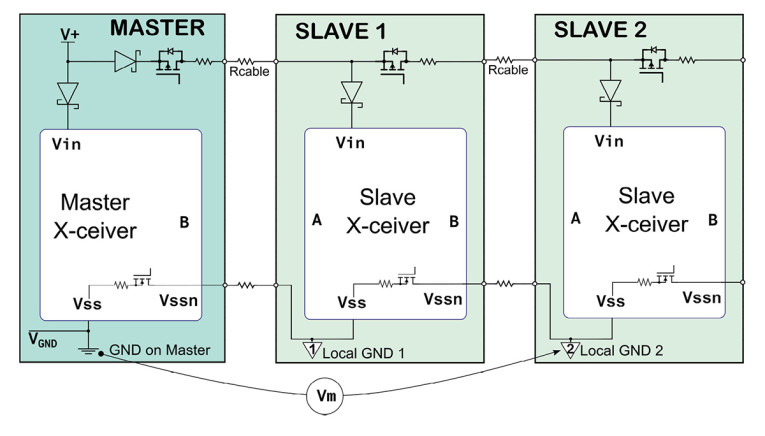
This robustness to opens and shorts comes at a cost—Figure 4 should make that more obvious. The positive supply line will drop some voltage at each node due to the saturation voltage of the PMOS FET and the parasitic resistance of the cable and connectors. V+ and VGND are the power supply connections, and it’s reasonable to assume that VGND connects to a common earth ground via local supplies or common shielding connections between audio boxes.
Following the procedures in Analog Devices’ datasheet [3], an example of the three nodes shown in Figure 4 with 5 m total of 22 AWG, the resistance of the wire is about 0.26 Ω and the four connectors (assuming the DuraClik used on the EVM boards) equal 0.04 Ω for a total of about 0.3 Ω. The largest impedance comes from the VSSN to VSS NMOS transistor at about 1.2 Ω, from the second node this is about 2.7 Ω total. If two slaves were drawing 50 to 100 mA each, then we could approximate the voltage at Local GND 2 as around 200 mV relative to the master node’s GND signal (Vm in Figure 4).
If the slave nodes are all microphones, then the noise on the Local GND will not affect operation. If a slave node has ADCs or DACs, they will be referenced to the Local GND. If those connect to external devices that have a (system) ground connection, a ground loop is created, leading to increased noise. The A2B fault detection is also compromised by the alternate ground path.
In Figure 4, we see that the available voltage at each node drops as the positive supply line will also have some parasitic resistance, though the PMOS switch has much lower impedance than the NMOS VSSN one in the transceiver IC. Analog Devices offers a spreadsheet to aid in calculating the power node power and voltage needs (see Resources).
Another complication is possible if shielded cable is used. Shielded cable is avoided in automotive use because of the extra weight and cost. In the automotive case, there are tweaks that can be made as the node configurations are fixed and precise wire routes are known. That will not be the case in other applications.
While automotive electromagnetic compatibility (EMC) is more stringent than Federal Communications Commission (FCC)/CE Mark requirements, audio applications need to avoid creating even small amounts of EMC as at some point low-level analog signals will exist and be very susceptible to small signals (think radio stations miles away coming through a mic pre-amp).
Connecting shields to local grounds at each node creates an alternative ground path and a way for the system to radiate. The cable shield should connect to the metallic chassis (if present) and for where the local ground DC value is not the system 0 V value, connect to the local ground via a small value capacitor, possibly in parallel with a resistance of a few mega-ohms.
This capacitor provides an AC ground — if everything is at the same potential it can’t radiate. Minor circuit imbalances can degrade this approach. If the shield starts carrying high-frequency signals (with A2B primarily 50 MHz and with harmonics stretching out to the 200+ MHz range), the relatively long lengths of interconnect cable act like an antenna. These problems are not new to high-speed digital system designers, but they may not have been experienced when working with analog-only audio systems.
A2B System Application
There are two obvious applications for A2B where phantom power is very helpful and the system grounding issues won’t be problematic like they might be between boxes of audio electronics. Specifically microphone and headphone applications do not involve interconnections to multiple endpoints and don’t present a grounding problem.
A single microphone is perhaps overkill to throw at A2B, however, the use of VR audio recording via high-order Ambisonics is an excellent fit for sending multiple channels of microphone audio through a single twisted pair and not worrying about noise pickup or a massive multichannel XLR snake.
A conventional stereo headphone over A2B is easy enough, but overlooks the new capability that A2B can offer. With A2B, multiple channels of audio can be sent broadcast-style and a small DSP that the user controls can select levels and adjustments to create a unique local listening experience from a common set of audio streams routed to multiple headphone endpoints.
Combining both the microphone and the headphone concepts opens up interesting possibilities for field recording, measurement, and monitoring. For both of these applications A2B can be used as a point-to-point link to some head end box (up to 15 m cable length), as to run it in a daisy chain two cables (four wires) are needed so that the chain can continue to the next device. Alternately, we can take advantage of an A2B capability that hasn’t been discussed yet: the ability to have a branch off of the main A2B backbone (see Figure 5).
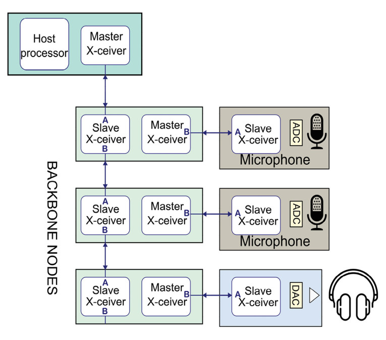
There are some topology limitations that are beyond the scope of this introductory article, but six nodes in the backbone is a reasonable assumption. Latency will increase to around four sample periods to the end points (100 µsec) and the backbone nodes will probably need to be locally powered. The total distance from the farthest node can’t exceed 40 m, but 5 m spacing between the backbone nodes and 5 m cables to microphone arrays or locally controlled headphone endpoints fit a range of applications (e.g., specialized conference and media rooms, and small studio spaces for recording or streaming).
Summary
Part 2 of this article provided a closer look into A2B system design, bus topology, and phantom power features. In the next article we’ll examine A2B data transport and how to interface between peripherals and the A2B bus using parts made by Analog Devices, Inc. aX
Click here to read Part 1 of this article series
Click here to read Part 3 of this article series
Click here to read Part 4 of this article series
References
[1] IEC 61938:2018, “Multimedia Systems—Guide to the recommended characteristics of analogue interfaces to achieve interoperability,”
International Electrotechnical Commission, https://iectest.iec.ch
[2] AES 48-2019, “AES standard on interconnections—Grounding and EMC practices—Shields of connectors in audio equipment containing active circuitry,” Audio Engineering Society (AES), www.aes.org
[3] Adapted from AD2428 datasheet, Revision B, January 2020, Analog Devices, Inc. (ADI), AD2420(W)-AD2426(W)-AD2427(W)-AD2428(W)-AD2429(W), http://analog.com
Resources
A2B information, Analog Devices, Inc.,
www.analog.com/en/applications/technology/a2b-audio-bus.html
This article was originally published in audioXpress, November 2020.