
At one company, I became friends with Leo Taylor, who later got a fabulous job as a service tech for HP. Leo’s workbench included all the latest HP test equipment—storage oscilloscopes, signal generators, distortion analyzers, and more. Over a period of several years we met at his company every Monday night to design synthesizers and other audio devices.
Synthesizer Basics
One of the basic principles of analog synthesizers is voltage control. Rather than use only knobs to control the volume, or the pitch of an oscillator, or the cut-off frequency of a filter, in a synthesizer these are also varied by control voltages. So when you press a key on the keyboard, a voltage corresponding to that note is sent to a voltage-controlled oscillator (VCO). Another voltage that ramps up and down at user-defined rates feeds a voltage-controlled amplifier (VCA), and yet another varying voltage might go to a voltage-controlled filter (VCF) to add animation to the sound.
In what was surely one of the earliest attempts to sync a computer with an analog tape recorder, in 1970 Leo and I recorded a short tune, a modern three-part invention written by a friend of mine. We started by recording 60Hz hum onto one track of my Ampex AG-440 4-track professional recorder. That hum was then squared up — overdriven to clip and become a square wave — and played from the recorder into the control port of a small HP computer Leo borrowed from work. In 1970 a “small” computer was the size of a dormitory refrigerator!
Leo wrote a program in binary machine code to read the 60Hz sync tone recorded on Track 1, entering it one instruction at a time on the computer’s 16 front-panel toggle switches. There were no diskettes or portable hard drives back then either. The musical note data for the tune was also entered via the computer’s toggle switches. It took us 11½ hours to program the computer, enter the song data, and record the three tracks one at a time from control voltages output by the computer. You can hear the result in the file phils-hp.mp3 listed in Resources.
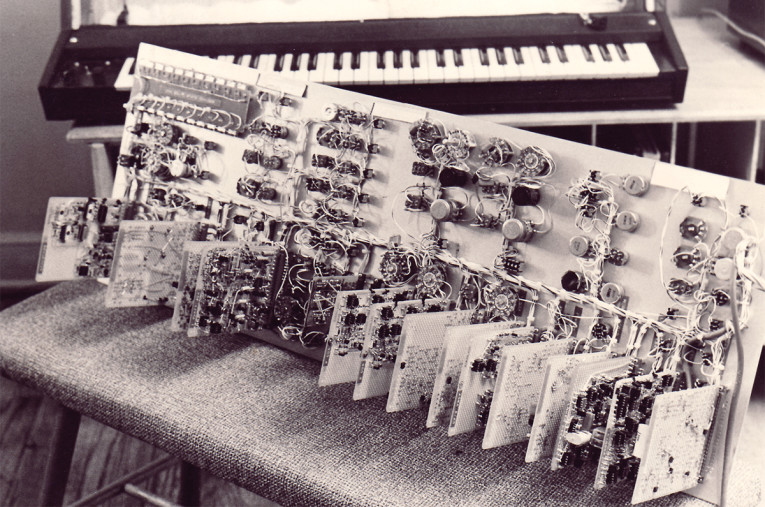
In 1974, I built another synthesizer, shown in Photo 1 and Photo 2. This one was much more ambitious than the first and included a 61-note keyboard, four audio oscillators, two VCFs and two VCAs, a low-frequency oscillator (LFO) for vibrato and tremolo, and portamento (glide from note to note). A 10-step sequencer was also included, along with circuitry to split the keyboard at any point so both synthesizer “halves” could be played simultaneously for a whopping two-note polyphony.

(Photo credit: Kevin Byron)
(Photo credit: Kevin Byron)
It took Leo and me two years to design this synthesizer, and I spent another nine months building it in the evenings. Leo was the real brains, though by the end of this project I had learned enough to design all the keyboard and control circuits myself. Fourteen separate plug-in circuit cards hold the various modules, and each card was hand-wired manually using crimped wiring posts and 24-gauge buss wire with Teflon sleeving.
Designing a Guitar Synthesizer
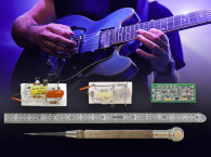
Fast forward to early 2021. I’m not much of a keyboard player, though I can pound out simple melodies and chords at half speed in a MIDI sequencer program. But my main instrument is the guitar. Where most synthesizers include a keyboard to play the musical notes, I wanted to be able to use my electric guitar. Guitar synths have been available for many years, but most require you to purchase a special guitar having separate pickups for each string. I decided to build one final synthesizer that I could play using my Fender Telecaster instead of a keyboard.
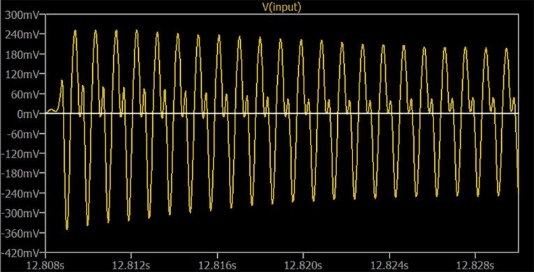
Reading the frequency of notes played by a string instrument reliably is the “holy grail” of guitar synthesizers. Unlike a static wave containing harmonics, such as square and sawtooth waves, the harmonics of a guitar or bass string vary in frequency as the string stretches and relaxes at the fundamental frequency. This creates “rolling harmonics” that ride up and down the fundamental when viewed on an oscilloscope. Figure 1 shows a note played high up on the guitar neck. Between the large fundamental cycles you can see smaller third harmonics whose level and position on the main wave change as the note sustains. So at the start of the note there are two extra zero crossings for each cycle, but 20ms later (at the right edge) there’s now only one zero crossing per cycle.
One common way to convert a frequency to an equivalent voltage is to generate a pulse having a fixed duration each time the input signal ascends through zero. These pulses are then accumulated and averaged by a low-pass filter. The higher the frequency, the more pulses that are accumulated, which creates a higher output voltage. But if the input wave passes through zero additional times due to the harmonics, the output voltage jumps one or more octaves higher than it should. So the first thing needed to read a guitar’s frequency is a filter that removes the harmonics. This is surprisingly more difficult to do than you might think, requiring a very steep filter!
My guitar synthesizer first filters out the harmonics, then an equivalent voltage is generated with a Period-to-Voltage converter (P2V) that measures the length (period) of each cycle. This has one big advantage over the more common Frequency-to-Voltage (F2V) converter described earlier. Instead of having to accumulate and average pulses over several cycles, a P2V converter assesses the time span between zero crossings. So it can determine the input frequency on the first cycle!
That voltage is then sent to Voltage-to-Period (V2P) oscillators that generate equivalent frequencies. When the note ends and the input voltage subsides, a noise gate senses the lack of signal and shuts off the guitar input. Then the last voltage that was measured can be held, similar to the Sustain pedal on a piano. Unfortunately, by the time the noise gate closes, the last voltage saved is invalid because the final bits of the note are mostly noise.
The Sample & Hold Time Machine
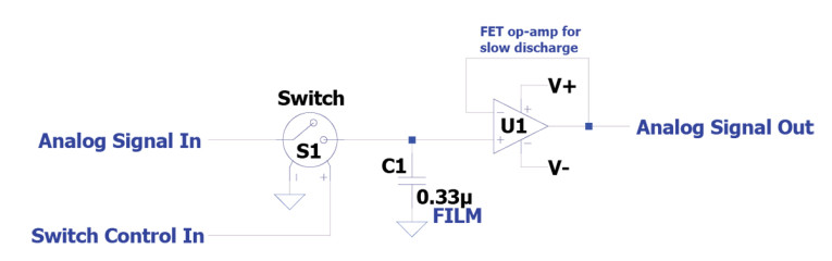
A Sample & Hold (S&H) circuit is very simple comprising a switch, a capacitor, and an op-amp or other “buffer” to prevent draining the voltage currently stored in the capacitor. Figure 2 shows a basic Sample & Hold circuit. The analog input passes through a voltage-controlled switch, which then charges a capacitor. Whenever the switch closes, the current input voltage is “sampled” and applied to the capacitor. Then when the switch opens, the capacitor’s present voltage continues to be sent to the output regardless of the input. That’s the “hold” part. An FET op-amp is often used because its input bias current is too small to drain the charge held in the capacitor.
To avoid sustaining the corrupt voltage that happens at the end of a guitar note requires looking back at least 20mS before the note ended, then quickly switch to sending that to the V2P oscillators. But it’s not enough to simply grab a backup voltage sample every 20mS because the previous sample might have been taken just before the current note ended. To do this reliably with analog electronics, a round-robin set of three S&H capacitors is needed to save the three most recent voltages. While a note plays, a single-pole three-throw (SP3T) electronic switch alternates sending the incoming P2V voltage stream to each S&H in turn. This makes available for output to the oscillators: 1) the current stream; 2) the sample taken and held less than 20mS earlier; or 3) the sample taken and held 20mS before that.
LTspice
Designing a large complex system, such as an entire synthesizer, is expensive and time consuming, buying and connecting hundreds of components. The freeware LTspice program from IC maker Analog Devices provides a fully stocked parts bin with a complete set of test gear. You just draw the schematic, then “run” it to see if it works. I used LTspice for my October 2017 Mojo Maestro article to determine the best resistor and capacitor values for that simple circuit. LTspice is a deep program with a modest learning curve. Thankfully there’s a very active support group that answers questions and offers advice. One huge feature of LTspice is it can accept input from a .wav file, and send output to a .wav file. This really helps when designing audio circuits!
Referring to the full S&H circuit in Figure 3, NE555 timer IC (U5) serves as an oscillator running at 50Hz (20 mS). This clocks a Modulo 3 Counter to generate the binary address sequence 0, 1, 2, 0, 1, 2 ... which directs Input Switch #1 (U3) to feed each S&H cap in turn. This switch has two address lines telling it which input should go to its output. In logic speak, LSB stands for Least Significant Bit and MSB is Most Significant Bit. Dedicated counter ICs are available, but it’s just as easy to create a counter using a pair of D Flip-Flops.
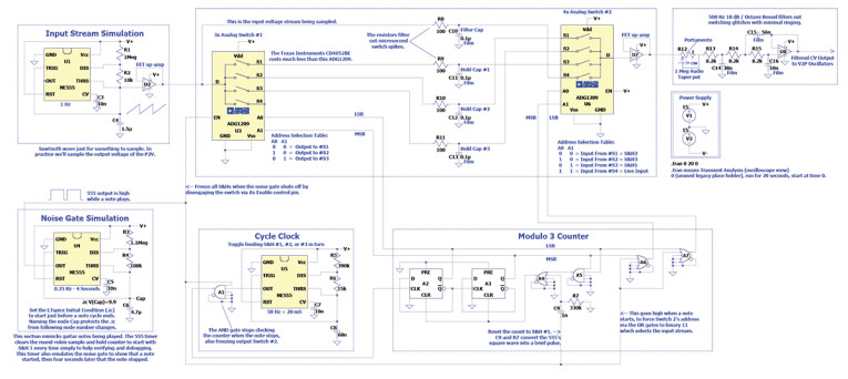
When a note starts and the noise gate opens, SP4T Output Switch #2 (U6) selects the incoming P2V voltage stream as its output to the V2P oscillators via OR gates A6 and A7. When the note stops, the most recently held sample is likely less than 20mS old, so we need to grab the sample that was captured and held before that one. One method subtracts 2 from the Counter address of Input Switch #1, then uses the result to tell Output Switch #2 which S&H was two counts earlier. But it’s even easier to use the same input switch address for the output switch, but swap around the output switch’s inputs. So if S&H #3 is active when the note ends, S&H #1 is selected for the output because it’s connected to the output switch’s input #3.
The incoming P2V voltage stream is not yet filtered to average out the occasional errant cycle that could cause an audible glitch. So after choosing between S&H #1 through #3, Output Switch #2 feeds the Portamento control (set to 1Ω in the schematic to disable it), then a three-pole low-pass filter. This filter applies minimal averaging to the datastream, and also removes any brief spikes caused by capacitive leakage between the digital and analog paths within Switch #2. Likewise, simple RC filters are placed after the input switch for the same reason, though they’re not strictly needed. The ADG1209 and CD4052BE switches referenced in the Figure 3 schematic have an internal On resistance of around 120Ω. So R8 through R11 simply add a little more resistance. I used the Analog Devices ADG1209 switch because I couldn’t find a component model for the less expensive CD4052BE. aX
Author’s Note: The schematics for this article are in PDF files you can download from the Project Files link. This lets you zoom in to read them more clearly.
Digital Logic in LTspice
Logic ICs are used to make logical decisions in both analog and digital circuits. For example, if a voltage comparator has a positive output and a timer IC is still active, an AND gate will output a “1” (positive voltage). An OR gate is similar, outputting a 1 if any of its inputs—1 OR 2 OR 3—are positive. There are thousands of logic ICs available, so rather than provide all those component models LTspice offers generic versions that are highly flexible. The AND and OR gates each have five inputs, with both normal 1 and reversed 0 outputs. So the same AND gate can also serve as a NAND (Not AND) gate. In Figure 3, the outputs with the little circle are the “Not” output connections. When more than five inputs are needed, multiple gates can be daisy-chained together.
There isn’t room to describe all of the logic devices LTspice provides, but I’ll mention the D Flip-Flops A2 and A3 since they’re used in the Sample & Hold circuit. Flip-Flop means the output goes back and forth between the two states 1 and 0, and the “D” stands for Data. This component is often called a D-Flop for brevity. When a 1 arrives at the Clock input, whichever value — 0 or 1 — is present at the Data input is sent to the Q (normal) output. The “Q-bar” output is always the opposite polarity of the Q output, much like the Not output of the AND and OR gates. So one use for a D-Flop is to save one bit of memory. You put a 1 at its input, send a clock pulse, and that 1 is remembered until the next clock pulse. However, D-Flops also have Preset and Clear inputs, to force the Q output to 1 or 0, respectively, regardless of the Data and Clock inputs.
With all of the LTspice digital components, any inputs or outputs that are not used should be grounded. This tells LTspice not to waste time computing those connections. Of course, in a real circuit you’d never connect an unused output to ground! For mixed analog and digital circuits like this Sample & Hold, you also need to specify the input and output operating voltages. Most logic chips work at either 3V or 5V, but this circuit uses 15V power supplies. If you download the project file, right-click on any of the digital parts and you’ll see two user-defined values: Vhigh 15 and tD 10n. The first sets the operating voltage to 15, common with CMOS logic chips, and the second creates a propagation delay of 10 nanoseconds through the component. Most digital logic circuits work correctly with no delay, but some circuits cross-connect outputs to inputs and can lock up without this delay. So it’s good practice to always add the delay.
Project Files
To download additional material and files, including the Sample & Hold LTspice file, visit
http://audioxpress.com/page/audioXpress-Supplementary-Material.html
Resources
HP computer synthesizer tune: http://ethanwiner.com/phils-hp.mp3
LTspice:
www.analog.com/en/design-center/design-tools-and-calculators/ltspice-simulator.html
LTspice online support forum: https://groups.io/g/LTspice
E. Winer, “Build the Mojo Maestro,” audioXpress, October 2017,
Read the other articles in this Building a Guitar-Controlled Synthesizer series
Part 2 - Frequency to Volts and Back
Part 3 - LFO and ADSR
Part 4 - Input Section
Part 5 - VCA and VCF
This article was originally published in audioXpress, April 2022.