There are two pieces needed to process input from an electric guitar: the input section’s preamplifier and noise gate, and the pick detector. The preamp amplifies the weak signal from an electric guitar’s pickup and brings it up to line level for further processing. The noise gate detects when a note is currently playing and when it stops. Of course, the pick detector signals each time a new note is picked.
As with the previous synthesizer components in this series, the circuits in this article were developed using the LTspice program available for free from IC maker Analog Devices. One terrific feature of LTspice is its ability to accept input from a .wav file, and also output voltages as audio to a .wav file. Under Project Files is a link to a Zip file with the LTspice circuit file shown in Figure 1, plus the small .wav file this circuit expects as input.
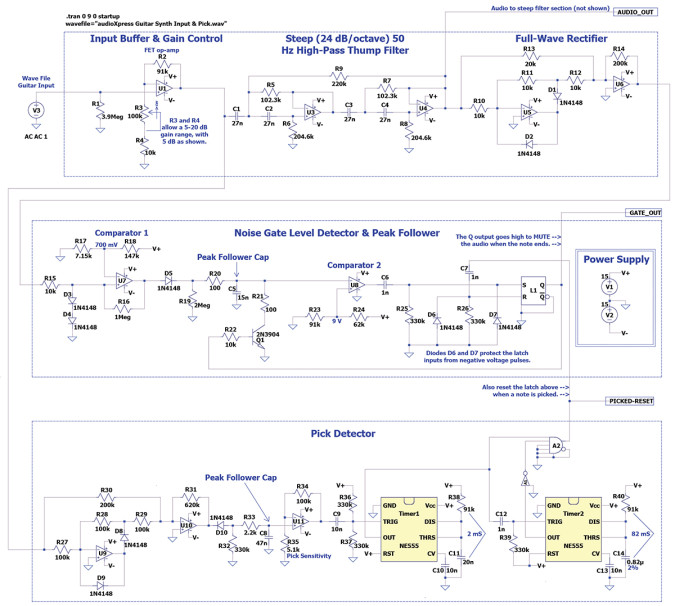
Input Section
In LTspice, full scale (0 dBFS) in an input .wav file comes into the circuit at ±1V or 2V peak-to-peak. This is shown in the Figure 2 screen-capture from Sound Forge, the audio editing software I use. Passive electric guitar pickups output somewhere around 250mV, depending on many factors. So the example .wav file this circuit requires was set to output that amount from voltage source V3. Note the wave file metacommand at the top left of the schematic. This is how you tell LTspice to use a file for input rather than a sine wave or other more common input test signals.

Passive guitar pickups sound best, and give the flattest response, when driving a high impedance input. Most guitar-based effects have an input impedance of at least 1MΩ (one million ohms), but even higher never hurts. So R1 in the input preamp is 3.9M, and op-amp U1 is an FET-type, which further ensures a high input impedance. LTspice doesn’t have a potentiometer component, so resistor R3 had to be drawn that way using line art. In the real circuit R3 will be a user-accessible 100kΩ potentiometer that sets the overall system gain. In practice this could be either an internal trimpot, or an external control if the device will be used with more than one electric guitar. With the R2 through R4 values shown, the preamp has a gain range of about 5dB to 20dB.
After the preamp, the guitar signal passes through a very steep 50Hz four-pole high-pass filter to remove the “thumps” that can happen when a guitar player rests his hands on the strings. The lowest note with standard guitar tuning is the low E at 82.4Hz, so this filter’s frequency is too low to affect that. The 220kΩ resistor R9 provides a small amount of positive feedback to help flatten the pass-band response.
The Thump filter then feeds a full-wave no-drop rectifier that outputs a positive-going version of the signal whether the input is positive or negative. Musical instrument waveforms are often asymmetrical, and guitar players can pluck a string either up or down, so this circuit must be able to respond to ether polarity of the input. A normal full-wave rectifier found in power supplies loses 0.6V across each rectifying diode, and that would be unacceptable here given the relatively small signal voltages. Placing the diodes within the feedback loop of op-amp U5 avoids that voltage drop. Op-amp U6 then applies 20dB additional gain via R14 to bring the signal up even higher for more accurate processing in the sections that follow. (For unity gain in the rectifier R14 would be 20kΩ instead of 200kΩ.)
Noise Gate Level Detector & Peak Follower
Next, the rectified guitar signal passes through two voltage comparators. Guitar notes tend to fade out quickly, so a pair of “clipping” diodes at the input to U7 limit the waveform peaks to around 1.2V, which keeps the voltages more uniform as they decay and thus easier to process. Since op-amp comparator U7 outputs a healthy 15V, the small drop in diode D5 is irrelevant.
My earlier article (audioXpress, June 2022) showing the LFO and ADSR modules explained the concept of hysteresis, whereby a controlled amount of positive feedback is applied to preserve a system’s state. In that article I used as an example, “Don’t turn off the furnace until you get slightly above the temperature I set.” That LFO circuit uses a large amount of hysteresis around an op-amp comparator to generate its large square wave output. The comparator doesn’t flip states until the input voltage is almost as high as the power supply! In the Noise Gate shown here, op-amp comparator U7 uses only a small amount of hysteresis via R15 and R16, to minimize the comparator constantly flipping states within each guitar wave cycle.
A peak follower circuit usually charges a capacitor with a varying voltage through a diode, and that voltage is buffered by an op-amp to isolate the capacitor from being drained by the circuits that follow. In this case the input is the fixed-level output from comparator U7, and the next circuit element is an op-amp comparator that serves as a buffer. So the capacitor alone can be considered the peak follower.
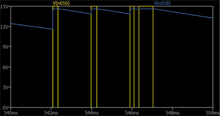
Where Comparator 1 in U7 assesses the individual cycles in the incoming guitar wave, Comparator 2 in U8 instead looks at the larger picture to identify each note’s On and Off times. Figure 3 probes several places in the circuit at once to better show how they all interact. The brown trace is the guitar wave at the output of U6 after rectification, so it extends in the positive direction only. The red trace is the 0.7V loudness reference for Comparator 1, and the yellow trace is the output of Comparator 1 U7. Even though the reference level for Comparator 1 is set to 0.7V, its output doesn’t flip positive until the input level reaches 0.9V due to the hysteresis set by resistors R15 and R16. Then when the guitar wave drops back down, the comparator’s output doesn’t go negative until the voltage drops to below 0.6V.

Figure 4 shows the output of Comparator 1 in yellow, but this time along with the voltage at Peak Follower capacitor C5 in blue. As long as the comparator continues to switch positive on the incoming guitar wave peaks, C5 keeps getting pumped up toward the 15V power supply. That C5 voltage then goes to Comparator 2, whose output is shown as red in Figure 5. Here, the virtual oscilloscope is zoomed way out to see entire note durations rather than individual wave cycles. As the guitar’s current note fades out and C5 stops being charged, Comparator 2 waits for C5 in blue to fall below 9V. At that point the note is considered to have ended and Comparator 2 flips positive.

The times and the comparator voltage levels in these circuits are somewhat critical. If the peak follower’s decay time is fast (if R19 is smaller), Comparator 2 can “chatter” (quickly flip back and forth repeatedly) even though there is some hysteresis in Comparator 1. But if the decay time is too slow, noise residue at the end of a fading note continues to get through until the cap drains fully. To avoid this, when Comparator 2 decides the note has ended, it sets latch L1, which dumps the peak follower capacitor, forcing a low input level to Comparator 2 to avoid repeated switching. The latch is then reset the next time a note is picked. (The sidebar briefly explains digital latches.) Note that Comparator 1 needs to run on ±15V rather than just +15V to keep the up and down hysteresis thresholds more symmetrical.
Pick Detector
Like the Noise Gate that needs to recognize both positive and negative voltage peaks, the pick detector also needs a full-wave rectifier. I probably could have used the same rectifier circuit that’s in the gate section, but this one needs to output a negative voltage and it requires less gain. It also seems to work better taking its input from before the 50Hz high-pass “thump” filter. Electronic components are cheap, so I just added a new separate circuit. This rectifier drives a second peak follower capacitor, C8, whose buffer op-amp adds yet more gain. That triggers a 555 timer IC to create the 2mS pulse signaling that a note was picked on the guitar.
A 555 timer chip begins its cycle of outputting a positive voltage when the Trigger input transits from above to below one-third the supply voltage. So with a 15V power supply the trigger must extend down to below 5V. This is why more gain is needed in op-amp U11. But the trigger must be a brief pulse that ends before the timer’s period completes, otherwise the timer’s output will remain high. That is, a negative-going trigger starts the timing cycle, but if the trigger remains low the timer continues its positive output past its set time. The solution is the differentiator created with C9, R36, and R37.
Most differentiators convert a voltage step into a brief pulse using a series capacitor and one resistor tied either to ground or the power supply, depending on the required pulse direction. Figure 6 shows the left and right sides of capacitor C12 that triggers Timer 2 when Timer 1’s output goes negative after its 2mS period ends. Note that Timer 1’s Trigger input is biased to rest at half the supply voltage. This way the triggering signal can be as small as 2.5V. Here’s another clever little hack: To simplify calculating 555 times I use 91kΩ for the pull-up resistors (R38 and R40); then the timing capacitor’s value (C11 and C14) = mS/10 nF. For low-power circuits you can use 910kΩ, then mS= nF. Using “91” also works for microfarads (µF) as you can see in Timer2.
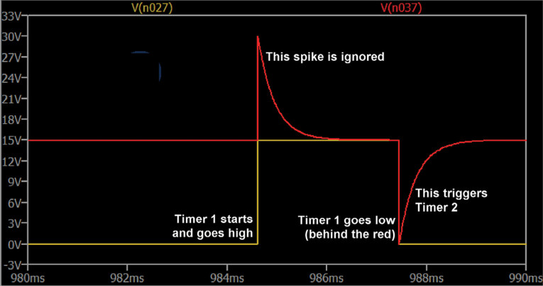
Figure 7 shows the output of rectifier U10 in brown, zoomed out to see two entire guitar notes. The voltage at Peak Follower capacitor C8 shown in yellow is 0.6V less due to the voltage drop across diode D10. Figure 8 adds to those displays the voltage at Timer 1’s Trigger input in red, after amplification and differentiation. This is now suitable for triggering Timer 1 to create the 2mS Picked pulse needed to start a note playing elsewhere in the synthesizer. But wait, we’re not quite done.


The initial few cycles of a picked guitar note are much larger than subsequent cycles as the note fades out. So it’s possible for Timer 1 to be triggered quickly two or three times in a row on those initial large wave cycles. To prevent this, Timer 2 is set for 82mS, and along with the AND gate serves to lock out additional Picked output pulses.
The logic is pretty simple: At rest, both Timer 1 and Timer 2 output 0 volts. But Timer 2 goes through an inverter, so that input to the AND gate is active, or “1.” Then when a note is picked and Timer 1 goes high, the AND gate’s output also goes high. But 2mS later Timer 1 completes, which triggers Timer 2 to start, so its inverted output goes negative disabling the AND gate for 82mS. This delay is long enough to avoid double-triggering, but still allows picking 16th notes at a tempo of 183 beats per minute (BPM), which is some very fast picking!
Finally, as explained in the previous articles, unused inputs and outputs of LTspice logic elements should be grounded. This avoids the program wasting time calculating connections that aren’t used. But once the LTspice simulation works as expected and you build the circuit for real, the inverting Q-Bar output of Latch L1, and the “NOT” output of AND gate A2, must be left floating, not grounded. This is also why three of the AND gate inputs are grounded. In this case they are disabled, not set to Logic 0.
Editor’s Note: All audioXpress articles from 2001 to present can be found on the aX Cache, a USB drive available from www.cc-webshop.com.
Digital Latches
A latch is a clever and useful digital logic element. Like the Data flip-flops used in the Sample & Hold and Period-To-Voltage Converter circuits shown previously, a latch can serve as one byte of memory. But a latch is more simple because it doesn’t need a Clock input to tell it when to store the data. You simply apply a logic 1 to its Set input “S” to store one bit, or to its Reset input “R” to clear its output to 0. And like the D-flop, it has both Q (normal) and Q-Bar (inverted) outputs. In the Noise Gate circuit, a latch is used to stabilize the gate’s output, so it won’t go on and off between the incoming guitar wave cycles. And like the 555 timers, both inputs are driven with a brief differentiator pulse to ensure that sustained input voltages are ignored. aX
Project Files
To download the links for LTspice circuit file and input Wave file, visit: http://audioxpress.com/page/audioXpress-Supplementary-Material.html
Recources
LTspice, www.analog.com/en/design-center/design-tools-and-calculators/ltspice-simulator.html
LTspice online support forum, https://groups.io/g/LTspice
Read the other articles in this Building a Guitar-Controlled Synthesizer series
Part 1 - The Sample and Hold Time Machine
Part 2 - Frequency to Volts and Back
Part 3 - LFO and ADSR
Part 5 - VCA and VCF
This article was originally published in audioXpress, July 2022