
I’ll show two different VCA circuits because one is much simpler, and works fine for one-off projects where precise unit-to-unit repeatability isn’t needed. The second one is similar to the VCA in the original Moog synthesizers, using a topology similar to the Moog VCF. But the VCAs are simpler so let’s start there.
VCA #1
In the 1970s, integrated circuits (IC) manufacturer National Semiconductor published a wonderful series of application books featuring its ICs and other products. National’s sales reps would give these paperback books away for free to electronic engineers, and I still have the complete series and refer to them often. The two I use most are the Linear Applications Handbook, and the Audio-Radio Handbook. But others in the series discuss TTL and CMOS digital logic, and both junction and field-effect transistors (JFETs and FETs). The first VCA circuit shown in Figure 1 is adapted from Linear Application Note AP129.

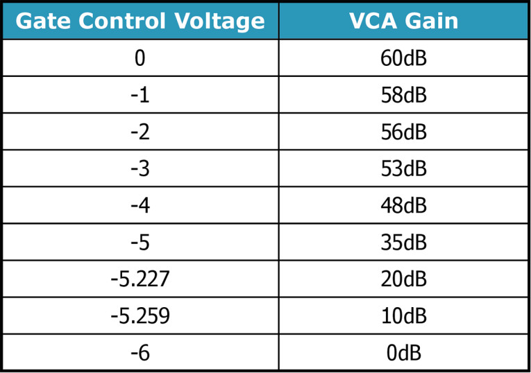
Although this circuit is simple, it has a gain range of 60dB — unity when the FET’s gate is at -6V, to +60dB when the gate is at 0 volts and the FET’s resistance is 30Ω. One downside is the ratio between control voltage and FET resistance isn’t linear. Further, the control voltage range can vary between FETs, even from the same batch, and especially between FET types. So the range -6V to 0 volts used in this LTspice emulation might be -4V to -1V, or some other range, with the FETs you buy. However, it works perfectly well as the VCA in a volume compressor where the correct control voltage is self-seeking based on the current audio output level (Table 1).
The distortion of this circuit is too low to measure reliably in the spice simulation, so it’s likely suitable for all but the most demanding hi-fi applications. Note the 60dB input attenuator that limits the signal level into U1 to 20mV to avoid clipping the output at maximum gain. If you don’t need the full 60dB gain range, raise R2 to 4.7kΩ and lower R3 to 3.3kΩ. This limits the range to only 40dB, but improves the signal-to-noise ratio (SNR) ratio by 20dB.
One problem with LTspice is that it doesn’t have all the latest semiconductor models in its component library. In this case the PN4391 FET is obsolete, so use the newer 2SK932-23-TB-E or almost any other small signal N-channel JFET. Likewise, noise in the op-amp can be a factor, so choose a current model such as the Texas Instruments OPA series.
I set up this circuit using two control voltage sources to provide different views into its operation. The file you can download is set to show the output for seven different control voltages at once when you probe the Audio_Output terminal. Each voltage is shown in a different color using the .step command. With .step, you specify a range of values for pretty much any circuit condition, and LTspice runs a series of simulations, one for each value in the range.
You simply assign a variable name (e.g., X or Y) to a component value, then tell .step to increment that variable. In this case, we’re stepping the output voltage from source V4, but .step can vary resistor and capacitor values, and most other component attributes. If you right-click the .step command line, a dialog pops up letting you specify useful options such as linear or log steps; starting, ending, and step values; or a list of discrete values (e.g., -5, 12, or 49).
I changed the LTspice color defaults to use the resistor color code, so the first trace is brown, then red, then orange, and so forth. When probing different parts of a circuit this makes it easier to keep track of which trace goes with which node in the circuit. With .step the same color sequence is also used, as shown in Figure 2.

Setting the waveform display colors to match the resistor code is easy: From the Tools menu select Control Panel, Waveforms (tab), then click Color Schemes. This brings up a dialog that lets you assign the color for each oscilloscope trace shown in the order you display them. Or in this case, the order that .step displays.
Unfortunately, .step doesn’t work in descending order, instead reversing the values to always be ascending. When I reported this problem in the LTspice Users Group, one of the experts there, Dave Bell, showed a simple work-around. In a circuit unrelated to this article I wanted to step resistor {X} backward from 21kΩ down to 1kΩ in 5kΩ increments. Dave demonstrated that changing {X} to {22k-X} forces the correct descending order. Note 22kΩ for the formula’s resistor value versus 21kΩ for the starting .step value, because the last step is 1kΩ (22 to 21).
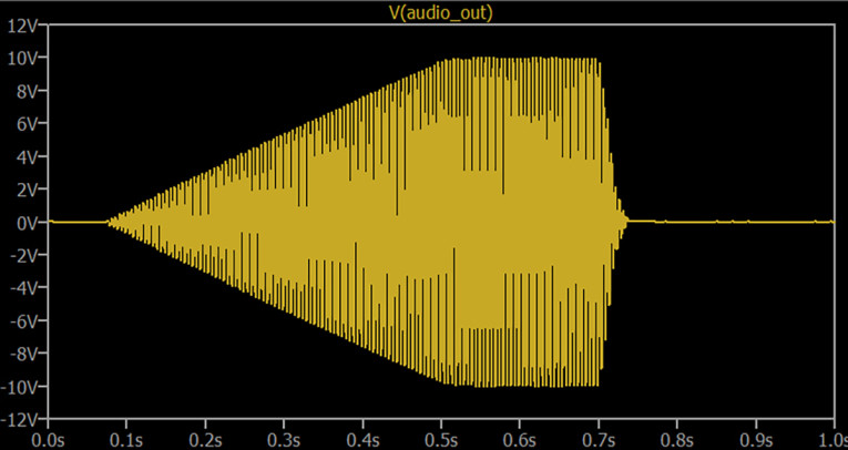
If you disconnect CV source V4 and connect V5, LTspice will display the gain change over time as shown in Figure 3. I set V5 to output a Pulse rather than a steady or stepped DC voltage. When a voltage source is set for Pulse you can control the initial voltage, rise time, destination voltage, number of cycles, and more. If you swap the CV sources as described, also change the audio sine wave to 200 cycles of 200Hz, change 0.1 in the .tran command to 1, then convert the .step command to a comment: Right-click the .step command line, click cancel, then you can select Comment to disable it. If you leave V4 set to {X} that will pop up a warning message you can ignore. Or change {X} to a number such as 3.
VCA #2
The core VCA design shown in Figure 4 is a linear current multiplier. It multiplies the input current into the bases of Q1 and Q2 times the collector current set by R12. As the inverted control voltage pulls down more and more on their emitters, the transistors conduct an increasing amount. We usually see an NPN emitter connected to ground either through a resistor or directly, with the input signal pulling up on the base. In this case, the bases are connected to ground, and the emitters are pulled down toward a negative voltage.

Since this is a differential pair, the input feeds only one side because the signal is the voltage difference between the transistor bases. But to preserve the critical circuit balance it’s important to use a dual transistor for Q1 and Q2, where both transistors are on the same die. There’s no need for another figure showing this VCA’s output because it’s nearly identical to Figure 2.
Of course, a standard common-emitter single transistor amplifier stage also multiplies current, but this circuit’s balanced design has several advantages. First, unlike the FET VCA, the gain change is perfectly linear, exactly tracking the amount of change in the control voltage. More important, as the control voltage varies the gain, the DC voltage on the transistor collectors shifts up and down in sync. By balancing the circuit with two equal collector currents feeding a differential op-amp input, the DC shift cancels out. So again the voltage difference at the collectors is the audio signal. Without this balancing act you’d get a thump when the control voltage changes, or a loud click if it changes quickly with a fast attack or decay from the ADSR.
This circuit is similar to the VCA that Robert Moog designed for his synthesizers, but was improved by Johan Verhoeven at Skull & Circuits to use a differential op-amp instead of a more complex arrangement of discrete transistors. I simplified the circuit further by removing some unnecessary components, and specifying 0.1% resistors for R3 and R4 to allow removing a trim pot. Readers interested in synthesizer circuits will enjoy the Skull & Circuits website. It’s a great source of schematics, and also fully assembled modules. The link is listed in Resources.
VCF
The circuit shown in Figure 5 is called a ladder filter because of the vertical arrangement of filter sections. Figure 6 shows how the filter’s response changes with different control voltages. The core circuit was designed by Robert Moog for his MiniMoog synthesizer, so I claim no credit for its elegant design! My only change was to alter the control voltage summing at the lower left to accommodate the various modules in my own guitar-controlled synthesizer. The patent for this filter expired decades ago, so it’s now public domain for anyone to use for any purpose.


As with VCA #2, this ladder filter pulls down on the bottom set of transistor emitters to change the impedance of the transistors above. Each upper transistor pair serves as one filter pole, so all four stages set the filter roll-off to 24dB per octave. Positive feedback through potentiometer R7 boosts the output of the filter at its cut-off frequency, which also increases the Q of that boost. On a real MiniMoog, the resonance can be increased enough to cause the filter to oscillate. The maximum amount of feedback available is set by R8, so you might need to reduce (or increase) its value slightly to resonate only at the very highest setting of R7. Note that the original Moog schematic specs R7 with a reverse audio taper, but a linear taper pot will be much easier to find.
This circuit is also balanced to avoid thumps and clicks at the audio output when the control voltage changes the frequency. As with VCA #2, matched transistor pairs are used to preserve the critical balance, but they’re needed only for the bottom pair below the ladder. Again, the BCM56DS is an excellent and affordable choice. It probably wouldn’t take much effort to replace the discrete transistor-based differential amplifier with an op-amp to save a few dozen components, as Johan Verhoeven did for VCA #2. But I left the schematic as is for its historical value, and to avoid inadvertently changing the filter’s highly esteemed sonic character.
The last item worth explaining in this filter circuit is Keyboard Tracking, whose voltage input is at the bottom left of Figure 5. Normally, a filter is swept automatically by its own ADSR as each note is played, or left at a static position, or varied manually by the musician for expression. Most analog synthesizers also have an option for the filter to track the keyboard, so playing higher notes shifts the filter frequency higher in addition to any sweeping or LFO effects. For example, if you have a resonant filter boost that brings out the third harmonic of a note, you’ll want the filter to track those notes as you play up and down the keyboard. Keyboard tracking also makes possible sound effects such as wind noise that can be varied in pitch or even played as a melody.
In order for the filter to precisely track the pitch of the current note, a potentiometer is needed. This could be an internal trim-pot on the filter’s circuit board, or a front panel control that lets the user scale the amount of tracking. But generally, when a note rises or lowers one octave, the filter’s cut-off frequency should go up or down the exact same amount. As noted on the schematic, R22 is actually a fixed resistor in series with a trimmer to precisely set a 1-to-1 ratio of note pitch versus filter frequency.
Finally, if you’d like to dig into the circuit’s internal operation you can switch the display from a stepped frequency response to the oscilloscope view. First, right-click the command line that currently specifies AC analysis:
.ac oct 50 10 20000
Then Cancel, then select Comment to disable it. Next, right-click this command which is now a comment, to enable Transient Analysis:
.tran 0 1 0
Then select “SPICE directive” to enable it. As with VCA #2, you should also disable the .step command, and change {X} to a number between 0 and 10 to set the filter’s cut-off to a single frequency manually.
Al Fine
Even if you don’t intend to build an entire analog synthesizer, the circuits shown throughout this series can serve as “cookbook” elements to use in other projects. When I started learning electronics in the 1960s there was no Internet. By the 1970s, I was in my 20s working as a technician at electronic companies, so I had access to real engineers who were kind enough to answer my beginner questions. I also got to read every issue of Electronics and EDN, excellent magazines offered for free to electronics engineers. In every issue both magazines offered clever circuit designs and interesting hacks, as well as industry news and product reviews. The National Semiconductor books mentioned earlier are another fabulous resource for “cookbook” style building blocks. Today, you can Google the name of a circuit type and come up with myriad circuits ranging from elegant to incompetent.
My point is that circuit elements like those presented in this series can be used and reused again and again. The Period-to-Voltage-to-Period article showed two types of Log converter circuits, a Sample & Hold, and simple ways to create octaves using basic digital logic chips. The LFO/ADSR article explained hysteresis and showed how to add that to a voltage comparator. The Input Section article shows how to make a noise gate, as well as a “no-drop” full-wave rectifier that avoids losing 0.6V across the diodes. That article also included a clever “cheat” showing how to easily select capacitor values for the 555 timer IC. This article shows how to make two types of voltage controlled amplifiers plus the classic Moog low-pass filter.
This is how I learned how to design electronic circuits, by piecing together smaller building blocks from magazines, and the application notes from semiconductor makers. I don’t have a degree in electronics, and I’m no math expert! But I can assemble circuit elements and eventually come up with something that works. Online calculators for every type of filter are readily available, saving you time and effort to find suitable resistor and capacitor values. In the old days you’d have to solve formulas such as:
ƒc = 1 / (2 × π × R × C)
again and again as you experiment with different frequencies in a high-pass filter. The LTspice software I used in all of these articles is vastly easier and faster—and much less expensive! — than actually building and modifying circuits and owning a bench full of test gear. Indeed, life today is good for electronics hobbyists. aX
Project Files
To download the links for LTspice VCA circuit file: [VCA-FET.asc]; the LTspice VCA circuit file: [VCA.asc]; and the LTspice VCF circuit file: [VCF.asc], visit:
http://audioxpress.com/page/audioXpress-Supplementary-Material.html
Recources
LTspice, www.analog.com/en/design-center/design-tools-and-calculators/ltspice-simulator.html
LTspice online support forum, https://groups.io/g/LTspice
National Semiconductor’s Applications Notes handbooks, https://archive.org/details/manuals-nationalsemiconductor
Skull & Circuits, www.skullandcircuits.com
E. Winer, “Building a Guitar-Controlled Synthesizer: The Sample & Hold Time Machine,” audioXpress, April 2022.
E. Winer, “Building a Guitar-Controlled Synthesizer: Frequency to Volts and Back,” audioXpress, May 2022.
E. Winer, “Building a Guitar-Controlled Synthesizer: LFO and ADSR,” audioXpress, June 2022.
E. Winer, “Building a Guitar-Controlled Synthesizer: Input Section & Pick Detector,” audioXpress, July 2022.
Read the other articles in this Building a Guitar-Controlled Synthesizer series
Part 1 - The Sample and Hold Time Machine
Part 2 - Frequency to Volts and Back
Part 3 - LFO and ADSR
Part 4 - Input Section
This article was originally published in audioXpress, August 2022.