The compressor circuit described in this article is designed to balance the volume of speech that varies in level by 40dB or more. Where most compressors have a threshold control that limits the maximum volume allowed, this circuit does the opposite: It leaves loud content alone and “reaches down” to raise up the level of soft parts. I occasionally use a Zoom portable recorder to record multiple people talking, and the volumes can vary quite a lot making the softer people difficult to understand. When using a typical compressor, you have to squash the loud parts severely in order to raise the soft stuff enough. That usually adds unwanted artifacts. But the compressor described in this article remains very clean with minimal side effects, even when set to raise ultra-soft content more than 40dB.
Things That Didn’t Work
Learning what doesn’t work is just as educational as knowing what does work. I had several failures and false starts with this project, and I’m glad to share all the things that went wrong!
At the heart of every compressor is a voltage-controlled amplifier (VCA) that lets the circuit vary the volume automatically. In my previous Guitar Synthesizer series, I showed two types of VCA circuits [1]. Unfortunately, neither is suitable for a professional quality audio product because their distortion is fairly high, varying with signal level. Adding a little distortion to a synthesizer or electric guitar often helps the sound. But that’s not wanted here. So first I tried a “chopping” circuit that interrupts the audio at an ultrasonic rate, as shown in Figure 1. Interrupting a voltage at an ultrasonic rate with a varying duty cycle (on versus off time) to control the volume is not unlike the way Class-D audio power amplifiers work.
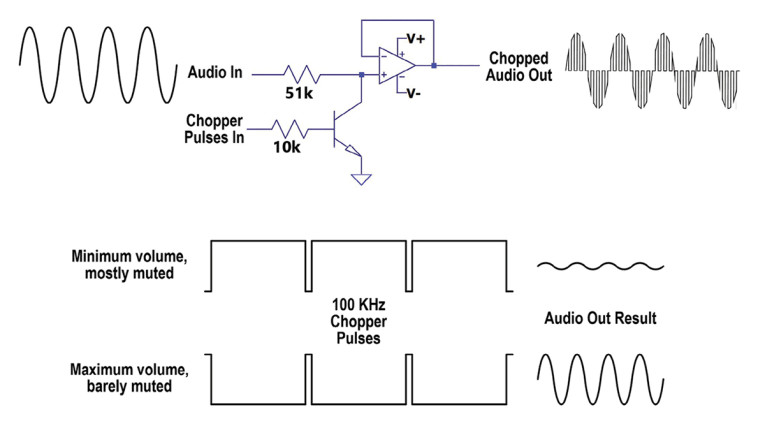
When the transistor near the top of Figure 1 is fed the high-frequency pulse wave from below, it mutes the audio for a length of time (microseconds) based on the wave’s current duty cycle. Unfortunately, I was unable to vary the volume by more than 35dB because a one percent duty cycle at 100kHz — needed to attenuate 40dB — is a very short time period! Another problem was that LTspice, the simulation program I use to design audio circuits, ran slower than molasses because so many calculations are needed to track a 100kHz oscillator. Even with the clock at 50kHz it still took two hours to process 20 seconds of audio.
As luck would have it, while I was developing this circuit, Michael Blackmer — the son of David Blackmer of dbx fame — posted on his Facebook page the famous VCA circuit his father developed in the 1960s. The patent on this circuit expired long ago, but I asked Michael’s permission to use it anyway and he gladly agreed. So now I had a high-quality VCA with the incredible voltage-controlled gain range of –60dB to +60dB. More modern, even higher quality commercial versions of this VCA, are available from THAT Corp. (see Resources).
Most compressors work by reducing the volume of the incoming audio when its level exceeds a user-defined threshold, also called a ceiling. The standard method monitors the output level, then reduces the input level when the output exceeds the threshold. One useful feature of this approach is the VCA doesn’t need a linear relation between the applied control voltage and the amount of gain reduction. Whenever the output level exceeds the threshold, the input is reduced as much as needed until that condition no longer exists. Because this circuit aims to raise soft content rather than reduce loud events, I decided to try monitoring the input rather than the output. The input level would then anticipate how much gain is needed to raise the soft parts, to avoid adding artifacts due to rapid large gain changes.
Failure #2
I set up a full-wave rectifier and peak detector to output a DC voltage that tracks the current incoming signal level regardless of polarity to control the VCA’s gain. One problem is that Blackmer’s VCA responds logarithmically rather than linearly. So instead of doubling the control voltage to double the volume, you instead feed it in equal small steps. In this case steps of ±6mV raise or lower the volume by 1dB. But my peak detector tracks the incoming volume one-to-one linearly. So, I needed a way to compress voltages that double into equal rising steps.
Complex op-amp circuits are available to convert between linear and log voltages with great accuracy, and I showed several such circuits in Part 2 of my Guitar Synthesizer article series [2]. But it’s also possible to do this with one resistor and one diode! Figure 2 shows that part of the circuit. The op-amp outputs the DC voltage from the peak detector that tracks the incoming signal level. As the input level increases, more current flows through the resistor into the diode, which in turn raises the diode’s forward junction voltage
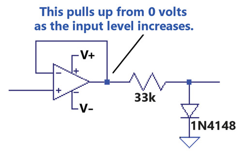
Figure 3 shows a series of sine waves that served as the input source. I set LTspice to use the resistor color codes when displaying a sequence of traces. So brown is the smallest voltage, followed by red, then orange, through blue. You can see that the sine waves progressively double in amplitude.
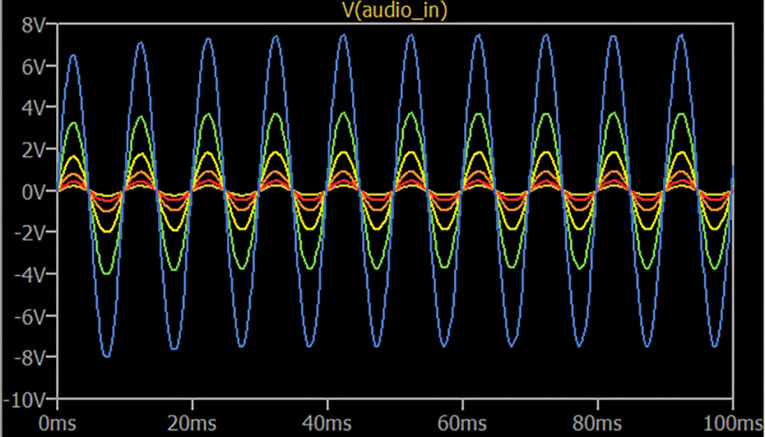
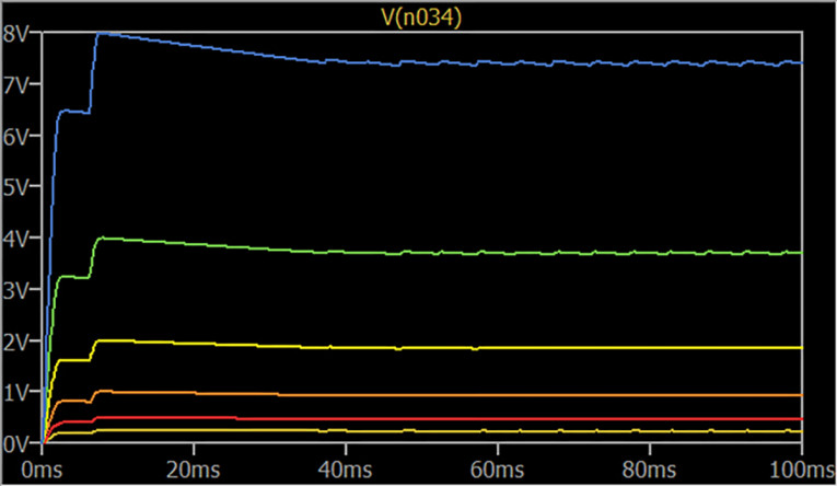
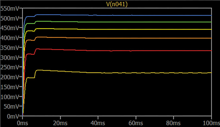
Figure 4 shows the DC voltages from the peak detector op-amp going into the resistor. These voltages also double successively. Then, Figure 5 plots the voltage where the resistor feeds the diode, to show how the diode “clamps” the voltages at a logarithmic rate as the current through it increases. The brown and red traces aren’t exactly logarithmic because they’re below the threshold where the diode begins to conduct. Many people consider common silicon diodes to conduct starting around 0.6V, but Figure 5 shows that conduction actually begins much lower, just above 300mV.
This simple log conversion worked well enough to control a reasonably wide range of signal levels but assessing the input level rather than the output never worked very well. No matter how I massaged the control voltages, the output level was never as consistent as I wanted. I abandoned that idea and changed to monitoring the output as is most common. This avoided the need for a log converter, but I still needed a way to reverse the usual operation to raise soft content rather than lower the loud parts.
What Goes Down Must Come Up
All compressors possess attack and release times, where the attack time determines how quickly a loud event is reduced and the release time sets how long it takes to raise the volume back up. For many applications, the attack time must be as fast as possible. Otherwise, a disturbing loud burst will get through briefly, likely causing distortion. The release time can be fast or slow, depending on the application. However, when both the attack and release times are fast, every compressor suffers from an irritating side effect known as “pumping and breathing” when the constant volume changes vary the background noise level. Distortion also increases at low frequencies because the rapid level changes begin to track each wave cycle. This tends to flatten the wave tops, so the result is more like clipping than compressing.
Most compressors let you control attack time, release time, and threshold. The circuit in this article instead has user controls for only input gain and depth — how far down the compressor will reach to raise soft content up to full scale. The attack time must be fast, as explained earlier. But the release time must also be fast, so someone speaking softly or from far away, immediately after a loud person, will be made louder quickly enough to not lose their first few words. To avoid distortion and pumping artifacts due to both the attack and release being fast, I added a brief delay to the level comparator that disallows volume changes less than 300 milliseconds apart. Let’s take a closer look at the whole circuit.
The Whole Enchilada
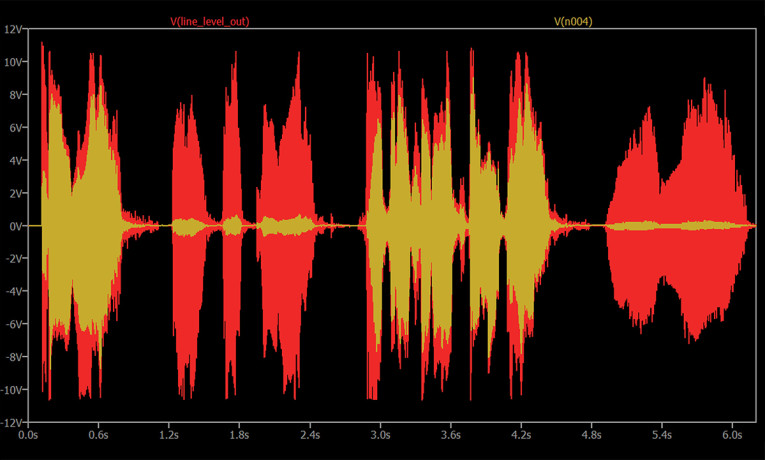
Figure 6 shows the entire circuit in detail. So far, this circuit exists only as a file for simulation in LTspice, but it will work the same when built as a hardware device. We’ll start with the input section, which is balanced since I consider this a “professional” level design. Gain resistor R4 is set to 1Ω, but it’s really a 20kΩ potentiometer turned fully clockwise. This allows a gain range of 6dB to 20dB, with the gain at 20dB as shown. When both the Plus and Minus inputs are actively driven the gain will be 6dB greater. The Wave file used here is just for the simulation, to get audio into the compressor. So only the Plus input is used. As a hardware device, input will normally come from a line level audio stream through an XLR connector or 0.25” TRS phone jack.
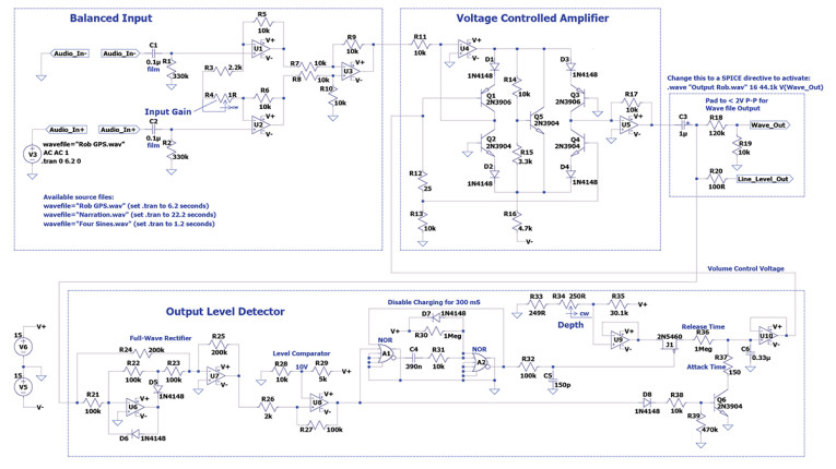
All rights reserved. Licensing offers are welcome.) See Suplementary Material for large version.
The line level output also feeds the full-wave rectifier at lower left. This ensures that the peak output level is detected correctly, regardless of which polarity dominates. The rectifier then feeds a comparator that trips at a fixed threshold of 10V, with R26 and R27 providing a small amount of hysteresis [3] to avoid constant “chattering” (flipping back and forth quickly) as the individual wave peaks pass through 10V. Now here’s where things start to get interesting.
The VCA’s control voltage derives from the wiper of Depth control R34. This control is shown as 250Ω, but it’s really a 500Ω potentiometer set to its middle. With the standard 1% values shown for R33 and R35, the Depth voltage can range from 123mV (20dB maximum VCA gain) through 365mV (61dB gain). As shown, with the pot in the middle, the wiper voltage is 246mV, which yields a “reach-down” VCA range of 40dB. This Depth voltage charges capacitor C6, which provides the actual control voltage. So, with no input signal, the voltage on C6 rises causing the VCA to reach the maximum gain, between 20dB and 61dB, based on the current Depth setting.
Now, whenever the amplified audio from the VCA exceeds 10V, the comparator flips positive. This attempts to dump the capacitor to zero volts via Q6, to reset the volume to minimum (unity gain). But the over-voltage condition comes and goes so quickly that the VCA gain never drops to zero; it’s reduced only enough to get the VCA output below 10V. The comparator also starts the Disable Charging timer. Rather than charge C6 directly from the buffered Depth voltage, FET switch J1 allows charging to be disabled by the 300ms timer. This means the gain can be reduced as much as needed immediately to prevent loud bursts from getting through, but it can’t go down and up more often than about three times per second.
Included Source Files
The compressor’s LTspice simulation file is available for download under Project Files. A more complete version of the schematic is also included, with additional comments and notes too small to see in the printed magazine. An LTspice file for just the dbx VCA is also included, so you can play with that separately or easily add it to your own projects. Finally, three separate input Wave files are provided so you can hear the compressor at work.
A few years ago, my comedian friend Rob Carlson and I created an alternate voice file for my Garmin GPS called California Stoner. So, I edited the “Turn Right” instruction to lower the volume severely in two places. Then I did similar edits on a longer narration file from one of my educational videos on YouTube. The last input file is a set of four sine waves, so you can probe the compressor’s circuits with a more stable input. aX
Project Files
To download additional material and files, including the LTspice files and input Wave files, visit our Supplementary Material section
References
[1] E. Winer, “Building a Guitar-Controlled Synthesizer: VCA & VCF,” audioXpress, August 2022
[2] E. Winer, “Building a Guitar-Controlled Synthesizer: Frequency to Volts and Back,” audioXpress, May 2022
[3] E. Winer, “Building a Guitar-Controlled Synthesizer: LFO and ADSR,” audioXpress, June 2022
Resources
“A Brief History of VCAs,” THAT Corp., https://thatcorp.com/a-brief-history-of-vcas/
R. Elliott, “VCA Techniques Investigated,” Elliott Sound Products, December 2012, https://sound-au.com/articles/vca-techniques.html
LTspice,
www.analog.com/en/resources/design-tools-and-calculators/ltspice-simulator.html
“Photo FET Optocouplers H11F1M, H11F2M, H11F3M,” OnSemi datatsheet, Semiconductor Components Industries, LLC, September 2022-Revision 3,
www.onsemi.com/pdf/datasheet/h11f3m-d.pdf
This article was originally published in audioXpress, July 2024