The best way to avoid popping Ps and Bs is at the source. Many people use a mesh screen filter in front of the microphone, but that’s not really necessary. Popping Ps are caused by air blasts from the performer’s mouth, so simply placing the microphone a few inches higher pointing down, or angled off to one side, will avoid this problem. But audio engineers often work after the fact and aren’t always able to control mic position. I hear popping Ps all the time on the radio and TV, especially from live on-the-scene reporters when the microphone is too close to their mouth.
What Is a Popping P?
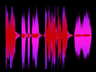
In a recording or podcast studio that pre-records content, popping Ps can be removed in an audio editing program. Software is available that can detect and remove popping Ps automatically, or you can do it manually. As shown in Figure 1, the basic method is to highlight just the pop sound, then either drop the volume about 15dB or apply a high-pass filter. This figure shows the word “Paris” three times in a row: First as the word exists in the file, then again with just the pop sound highlighted, and then after reducing the highlighted area’s volume by 15dB. When the file is played, the third (corrected) version now sounds like a normal P.

There’s no commercial device I know of that can remove popping Ps from a live audio stream. The circuit I developed and describe in this article can be used in recording or broadcast studios to repair the audio passing through their mixing board. As it turns out, removing popping Ps in real time is very difficult! The main problem is identifying the pop before it happens, so it can be fixed before even the first bit comes through. The low-pass filter that’s part of the detection circuit has 2mS of group delay below 300Hz. So, letting even that much of the pop sound through is unacceptable. Without this filter, loud normal speech might trigger the pop suppression. Therefore, the main audio stream needs to be delayed slightly so the pop detector can identify and suppress the pop starting just before it happens.
I used a 24-stage all-pass filter to delay only the lower frequencies of the main audio stream, but not the mids and highs. Creating the delay digitally would avoid having so many filter stages, but that raises several issues. With a digital delay, the mids and highs would also lag. If the person speaking also monitors through the device, hearing their voice delayed even a few milliseconds could be a problem. And if a crossover was used to delay only the lows, combining the delayed lows with the not-delayed mids and highs later could make a real mess of the response. As you may know, all-pass filters shift the phase delaying select frequencies, but they don’t change the response. Further, there’s no practical way I know of to include digital delay in the LTspice simulation program I used to develop this circuit.
I’ve described LTspice in several of my previous audioXpress articles, so I won’t belabor its many features here. A link to the download page for this terrific free program is listed under Resources, along with links to my previous articles that explain more about this program’s features.
Circuit Overview
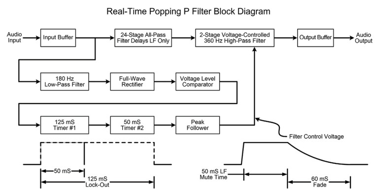
Figure 2 shows a block diagram of the circuit’s operation. I think it makes sense to describe the circuit’s basic operation here, then later I’ll discuss specific circuit details in the schematic. The input buffer presents a high input impedance to the audio source and isolates the source from affecting the low-pass and all-pass filters that follow. The all-pass filters delay frequencies below 300Hz to 400Hz by around two cycles, though it’s difficult to determine the exact amount of delay. Cumulative overlap between stages will increase the delay at some frequencies, and a given P pop might not align exactly with any stage’s center frequency yielding slightly less delay. The voltage-controlled high-pass filter does the real work of removing popping Ps by suppressing frequencies below 360Hz rolling off at 12dB per octave.
Detecting P pops isn’t too difficult. The low-pass filter helps to isolate the pop sound, then a full-wave rectifier converts that to only positive voltages. This way pops will be detected no matter which polarity dominates. Finally, a voltage comparator is set to trigger only when the filtered audio exceeds a given level indicating a popping P. It’s not shown here, but the schematic includes a “Pop Sensitivity” control to adjust for different signal and popping P levels.
The last stages create the control voltage that reduces low frequencies from the main audio stream. When the comparator’s output switches from 0V to the 15V supply it triggers two timers. The first timer starts the second one, holding its own output high for 125ms so the second timer can’t quickly re-trigger. Some popping Ps contain a single cycle that comes and goes quickly, but others will flip the comparator several times, even beyond the 50ms low-frequency mute time. So, the first timer locks out repeated triggering by the comparator for 1/8th second.
Finally, the peak follower is needed to allow ramping down the control voltage that drives the transistor mute switches. Switching the transistors on quickly to mute low frequencies isn’t a problem because the bulk of the audio—the pop—is being muted. But when the filter switches off letting the main audio through, a sudden DC level shift on that main audio would create a nasty pop of its own! You can see this level shift by temporarily removing capacitor C7, then probing the output of op-amp U8.
All-Pass Filters
Before we get to the complete schematic, let’s first consider how an all-pass filter works. In Figure 3, you can see that both the plus and minus inputs of an op-amp are driven at equal levels. The formula for the filter’s center frequency Fc is also shown. Frequencies well above Fc are shunted to ground through C1, so little signal gets to the plus input and instead goes through the op-amp’s inverting path at unity gain. Frequencies well below Fc are unaffected by C1, so they go through both the inverting and non-inverting paths. But the non-inverting path has a gain of 2 as set by R1 and R3, where the inverting path is unity gain. So the non-inverting path “wins” and also exits the op-amp at unity gain.
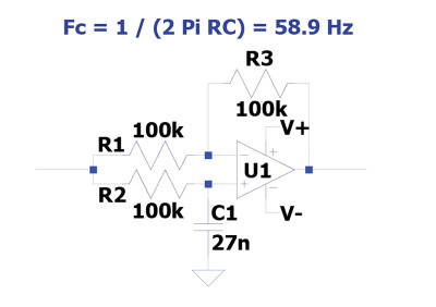
The “magic” happens for frequencies at or near Fc, because C1 takes time to charge through R2 creating phase shift that manifests as a time delay. All-pass filters are at the heart of musical instrument “phaser” effects to create the swooshing sound of comb filtering as the filter frequencies sweep up and down. Understand that this sound is not the phase shift itself! Even in fairly large amounts phase shift is inaudible. Rather, the hollow sound occurs when the source and phase-shifted outputs are combined. This creates a series of peaks and deep nulls in the response, and that is what you hear.
Figure 3 shows a single filter stage, though all-pass filters are typically used in pairs to avoid reversing the polarity of content above Fc. That is, two passes through an inverting op-amp restore the original polarity. Just as important, one stage can shift the phase no more than 90°, so two stages are needed to create a complete comb filter null in the response when used for a phaser effect. Most phaser effects use either six or eight stages, which creates either three or four peak-null pairs. You can optionally combine the source and phase-shifted outputs in opposite polarities to synthesize stereo from a mono source. That’s the basis of my DIY stereo synthesizer article from the June 1979 issue of Recording-engineer/producer magazine linked under Resources.
Details, Details
And now we get to the complete schematic shown in Figure 4. I formatted the schematic to fit nicely on a single magazine page (Figure 4 has also been included in the Supplementary Materials section located on the audioXpress website). As you read the descriptions below, use the component numbers R1, C2, U3, and so forth to follow the logical progression of the signal path. The top three rows are the all-pass filter stages, with the input just below on the left. We’ll start with the input rather than at the top of the page.
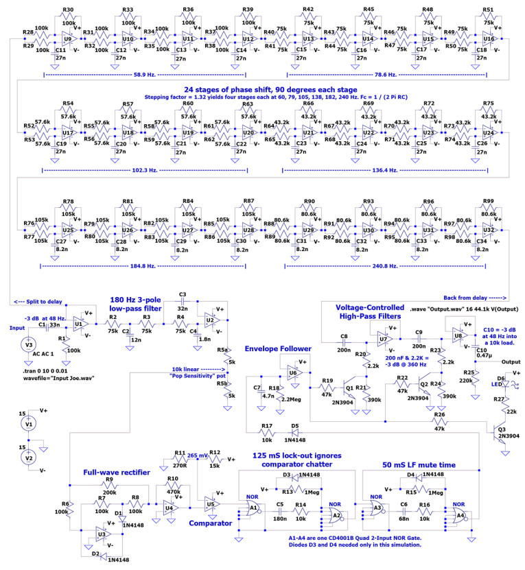
Input voltage source V3 is set inside LTspice for a function of None rather than the usual sine or pulse wave. The wave file Spice directive tells V3 to take its input from the file Input Joe.wav. There’s no reason to allow DC or subsonic content into the circuit, so C1 and R1 form a simple high-pass filter at 48Hz. As long as the source feeding this device has a low output impedance, which is typical, those filter component values should hold. A higher output impedance would do no harm, merely lowering the cut-off frequency a little. The output of U1 sends the wave file input to the all-pass filters above, and to a steep 180Hz low-pass filter as part of the pop detection.
LTspice doesn’t have a native potentiometer component, so resistors R5a and R5b substitute for the Sensitivity control. LTspice treats audio from a Wave file at 0dBFS as an input level of ±1V, or 2Vpp. Combined as a potentiometer, the R5 pair allows for signals half that amplitude when fully clockwise. If you expect to work with smaller input levels you can raise R10 or R12, or better, change U1 from a unity-gain follower to whatever amount of gain is needed. More gain at U1 puts the input signal that much higher above the all-pass filter’s noise floor. Another useful modification would be to configure the input to be fully balanced.
The full-wave rectifier in U3 and U4 is a standard circuit, as is comparator U5. When a pop larger than 265mV gets through the low-pass filter, the comparator’s output flips from 0V to 15V. This triggers the one-shot timer comprising NOR gates A1 and A2 to go high, which also starts the second timer. As mentioned, a loud pop might continue to trigger the comparator for longer than the 50ms low-frequency mute period. So, the first timer prevents any false triggers from muting the audio. Note that op-amps U4 through U6 connect their negative power feed to ground rather than to V-. These outputs never need to go below ground, and comparator U5 drives a logic chip whose input shouldn’t be allowed to go below ground.
One advantage of the NOR-based timers used here is that they can’t be re-triggered during their active timing period. So even though comparator U5 flips back and forth several times while a popping P is present, the timer’s output always remains high for 125ms. Diodes D3 and D4 prevent the reverse spikes from C5 and C6 from exceeding V+ by more than 0.6V. When A1’s output initially goes from V+ to ground, capacitor C5 follows. But 125ms later A1 goes high again, which sends C5 above 22V possibly damaging the input to A2. That spike also affects the timing for subsequent popping Ps because C5 starts its initial descent from 22V rather than from V+ which is 15V. However, the CD4001B NOR gates have protection diodes built in, so D3 and D4 are needed only for this simulation. At only 1% of the 1MΩ timing resistors R13 and R15, the 10kΩ current-limiting “safety” resistors R14 and R16 are too small to worry about.
There are thousands of logic ICs available, so rather than provide all those component models LTspice offers generic versions that are highly flexible. The AND and OR gates each have five inputs, with both normal 1 and reversed 0 “Not” outputs. This way OR gates can also serve as the NOR (Not OR) gates used here. In Figure 4, the outputs with the little circles are the NOR “Not” output connections, and the OR outputs are grounded to show they’re unused. With LTspice digital components, unused inputs or outputs should be grounded. This tells LTspice not to waste time computing those connections. Of course, in a real circuit you’d never connect an unused output to ground!
Op-amp U6 serves as an envelope follower, though there’s no real envelope to follow. You can see in Figure 2 how the positive output from NOR gate A4 is “sculpted” to mute the low frequencies quickly through R17, then recover back to a normal response at a slower rate through R18 to avoid creating its own popping sound. Diode D5 is also needed to avoid pulling the control voltage back down when the 50ms timer completes. U7 and U8 are simple high-pass filters, one pole each, tuned to reduce frequencies below 360Hz. When a popping P is detected, transistors Q1 and Q2 pull the 2.2kΩ resistors down to ground which enables the filtering through C8 and C9. Q3 is also triggered to light an LED showing that a pop was detected. Seeing when the pop suppression occurs can help when setting the Sensitivity control. I’ll also mention that if a source voice is very bassy and requires EQ, it’s better to reduce the level of low frequencies before sending the audio through the Popping P device rather than after.
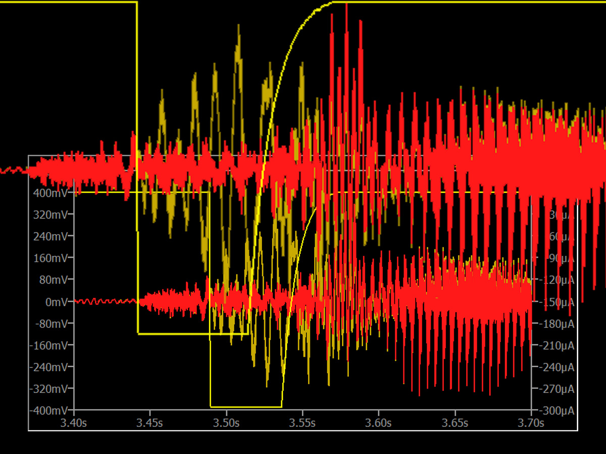
The LTspice file you can download under Project Files is set for oscilloscope view via the .tran directive. I encourage you to probe the various input and output points to better see how this circuit works. As one example, the brown trace in Figure 5 is the delayed audio as it exits the all-pass filter bank. The device’s final output is shown in red, and the yellow trace shows the current through R19 into the base of Q1. The brown input within the 50ms filter window shows several cycles of low frequency content at a large amplitude—the popping P. But that’s mostly missing from the red output signal.
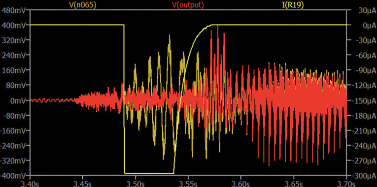
I set this image to show the current through R19 rather than the voltage output from the envelope follower because the follower’s output is much larger than the audio. This view keeps the vertical range to under half a volt making the audio large enough to see its details. When possible, displaying current rather than voltage can keep everything on screen clearly when monitoring both small and large voltages at the same time.
Because popping Ps can span a wide range of low frequencies, as high as 180Hz or possibly higher, I used six groups of all-pass filters having four stages of phase shift each. The correct way to divide the filter frequency range of 60Hz to 240Hz is logarithmic rather than linear. If the filters were spaced at equal 36Hz intervals they’d be too far apart at the low end and too close together at the top. I applied a “scaling factor” of 1.32 to determine each successive frequency. That is 1.32 times 60 is about 79, then times 1.32 again is about 105. This is similar to multiplying a musical note frequency by 1.0595 to get the frequency of the next note a half step higher. The comment in Figure 4 under the top row of filters shows the ideal target frequencies I calculated, and the numbers under each group show the actual frequencies based on the closest available 1 percent standard resistor values.
Note that I haven’t actually built this device. So far it exists only as an LTspice file. But the circuit is very straight-forward, so there’s no reason it won’t work the same when built. The only potential problem I’m aware of is the NOR gate timer periods could vary if the CD4001B inputs don’t transition at half-supply like LTspice gates do. If you build this, probe the input and output of both timers to confirm their active time spans. You can change either the capacitors or the 1MΩ resistors slightly if needed.
Demo Audio Files
Listed under Project Files are three sample wave files you can run through the circuit inside LTspice. Input Ethan is a file I created with the most exaggerated P pops I could muster. Input Joe was captured from a recent broadcast stream, and Input Rob is from a friend’s comedy show I videoed years ago. I also included a short MP3 demo showing Input Joe before and after removing the popping Ps, so readers can hear how well the circuit works without needing the LTspice program.
Author’s Note: This circuit is copyrighted but not patented. It’s offered for free for non-commercial use, and I welcome licensing offers for commercial manufacture. Contact me through my website: http://ethanwiner.com
Project Files
To download additional material and files, including Figure 4, the LTspice file and demo input wave files, visit: https://audioxpress.com/page/audioXpress-Supplementary-Material.html
Project Files for this article include:
Figure 4, Input Ethan.wav, Input Joe.wav, Input Rob.wav, Popping.asc, and Popping Demo.mp3
Resources
LTspice, www.analog.com/en/design-center/design-tools-and-calculators/ltspice-simulator.html
E. Winer, “Build a Stereo Synthesizer,” Recording-engineer/producer magazine, June 1979, http://ethanwiner.com/St-Synth.html
Previous articles by Ethan Winer that describe LTspice features:
E. Winer, “Building a Guitar-Controlled Synthesizer: Part 1 — The Sample & Hold Time Machine,”
audioXpress, April 2022, https://audioxpress.com/article/you-can-diy-building-a-guitar-controlled-synthesizer-the-sample-hold-time-machine
E. Winer, “Building a Guitar-Controlled Synthesizer: Part 3 — LFO and ADSR,” audioXpress, June 2022,
https://audioxpress.com/article/you-can-diy-building-a-guitar-controlled-synthesizer-lfo-and-adsr
E. Winer, “Building a Guitar-Controlled Synthesizer: Part 4 — Input Section,” audioXpress, July 2022,
https://audioxpress.com/article/you-can-diy-building-a-guitar-controlled-synthesizer-input-section-pick-detector
E. Winer, “Building a Guitar-Controlled Synthesizer: Part 5 — VCA and VCF,” audioXpress, August 2022,
https://audioxpress.com/article/you-can-diy-building-a-guitar-controlled-synthesizer-vca-vcf
This article was originally published in audioXpress, October 2023