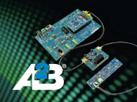
In the fall of 2020, I wrote a four-part article series (available online) discussing the basic concepts behind Analog Devices’ new Automotive Audio Bus (A2B) integrated circuits for transporting up to 32 audio channels plus control over a two-wire multi node network with a very low two-sample fixed latency between nodes.
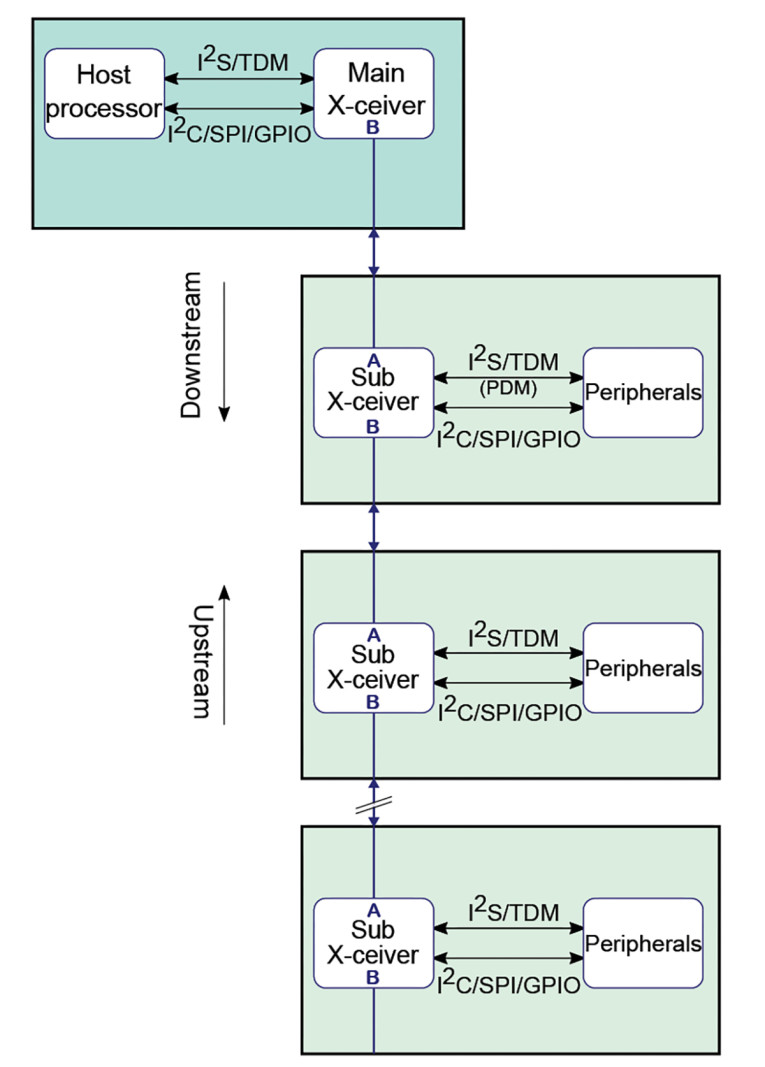
To conserve space we won’t go into the details covered in those earlier articles, but we will update the A2B system’s diagram (Figure 1) to include the third-generation capability being discussed here; counting generations as the AD2410 (and siblings) first generation, AD242x as second generation, and AD243x as third.
In Part 1, we’ll start with a review of a few key capabilities of A2B and then we’ll look at how the new AD2437 provides enhanced capabilities. Part 2 will dive deeper into the new bus power options, system design considerations, software and hardware development tools, and some shipping non-automotive audio products using A2B.
Key Capabilities
Audio can pass either upstream or downstream between any node(s); the only restriction is at any given node no more than 32 channels of 24-bit/48kHz audio can pass through in any given direction. Audio sample rates of 96kHz and 192kHz are supported, though with total channel counts of 16 or eight, respectively. The AD2437 provides a way to double these numbers by using a pair of devices and two twisted pairs. If the application can use 16-bit audio, then channel counts can be increased further.
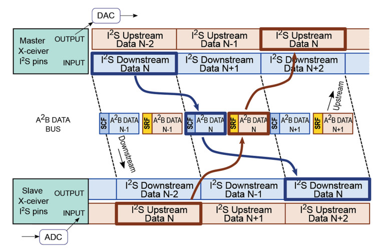
As illustrated in Figure 2, downstream audio data moves from the main node to the last sub-node in one sample period. Likewise upstream audio data moves from the last sub-node to the main node in the same sample period. A sample period is needed to capture the I2S data, and a few more microseconds for other data movement. This allows the fixed/deterministic latency between any I2S input and output in the system. For a full explanation of data movement and routing please see the earlier article series.
Getting Here
The first public announcements from Analog Devices about A2B appeared in 2014, though if you look back at the patents associated with A2B they were first filed in 2011. Work on the first parts was well under way when the announcements occurred, and in early 2015 Ford and Analog Devices released a joint press release on using A2B.
It wasn’t until 2018 that Analog Devices started making the AD242x parts available outside of automotive applications. Compared to the automotive supplier market, the general audio market is very diverse with thousands of different companies in business areas where A2B could have applications. There was not a large amount of uptake of the part outside of automotive areas despite solving several problems for distributed audio applications.
This cycle started to repeat with the AD243x series also focused on automotive applications. Automotive audio applications are generally limited in the distance between nodes and the total number of nodes compared to the broader audio market. Seeing an opportunity to overcome some objections for general use Analog Devices tweaked the device design to create the AD2437
Table 1 illustrates the improvements across the three generations of devices. Power use has gone up slightly with the AD2437, but it has more on chip peripherals and longer cable support. The actual power numbers in a specific application can vary considerably based on the amount of data on the bus and the local peripheral usage. Analog Devices provides a spreadsheet tool to calculate power under specific operational conditions. Outside of passenger vehicles power use can be less of an issue; being for wired devices battery operation is usually not a factor.
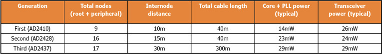
The AD2437’s much-improved internode and total cable length numbers opens the part up to more applications where things may be relatively close in physical sense but the wiring between them must follow a circuitous route. In addition to performance venues and larger conference and meeting room settings, these longer lengths are also found in transportation segments outside of passenger vehicles (e.g., planes, trains, and boats).
Even with the longer cable lengths supported by the AD2437, all audio path delays are constant between all nodes regardless of where audio is added and removed. The actual delay value is a little less than 50µsec (some settings can change this a little) or at 48kHz sample rate a little more than two samples.
Other New Features
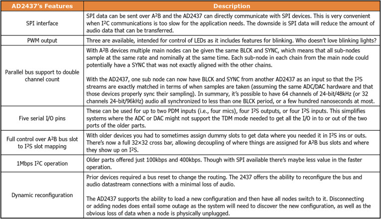
Table 2 highlights the AD2437’s new capabilities compared to the older generation devices. The SPI interface also opens up interesting possibilities for tunneling other data. Using a small microprocessor connected to the SPI interface would allow things such as UARTs or even 10M Ethernet to be tunneled over A2B. Given the audio focus of A2B MIDI is another obvious data tunneling application, there was a 2022 announcement from the MIDI Association to work out a standard implementation method.
Bus powered nodes are a complex subject but it’s important to have a firm grasp of the subtleties, both at the system level or as a designer creating A2B products. Skip this section at your own peril.
The AD243x introduced a new bus power scheme. Analog Devices named the original first and second generation schemes CFG0, and the new one used with the AD2437 is called CFG4, with the four simply being the bit you set in the power control register to enable this mode. CFG0 provides up to 9V with a total available power in bus powered segments of 2.7W.
In a CFG4 system that number is up to 24V with a total available power in a segment of 50W. This power limit is not the same as the total available power you can have on the bus; power can be injected anywhere in the A2B daisy chain and in more than one place.
Analog Devices has expanded what is meant by A2B bus power with the AD2437. Automotive users looking to minimize cable weight can use a two-wire connection with CFG4 to provide bus power to a node. Figure 3 provides a simplified view of this two-wire system. In real life, there are current sense resistors for both the supply/positive side and the return side. This allows sensing of various short and open circuits in the wiring to localize faults. An important capability for when there are a dozen nodes embedded in a vehicle cabin and you don’t want to rip everything out to find the bad wire.
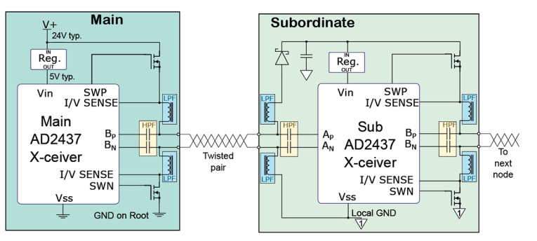
Looking at Figure 3, you can see that the ground connection on a bus powered node is not the same as the system ground connection. There will be some non-zero voltage associated with the IR drop of the cable(s) and connectors. If the bus node local ground was connected to the system ground (chassis in a vehicle), then the return current might flow through that path instead of through the main node, and the main node would sense the current imbalance as a fault condition. The earlier article series went into this topic in more detail and should be referred to for understanding the design of bus powered nodes.
Even if locally powered nodes are used, unintended ground paths can be a problem both for noise and EMI reasons; with A2B you also have the added consideration about the upstream node assuming a wiring fault due to current imbalance.
To understand the design implications of Figure 3 and CFG4 power, it is helpful to refer back to the earlier article series, which details the CFG0 power scheme. There, a high side PMOS switch is used, and the return side switch is inside the AD242x device. With the current limited to 300mA, this was practical. With the 24V 2A CFG4 system, external high and low side devices are needed. With the AD2437 the high side gate signal is boosted by about 5V over VBus to allow use of an NMOS device.
Not shown in the simplified view of Figure 3 are the current sense resistors for both low and high side and a couple of other resistors and capacitors associated with the sense and gate drive. The net result is the AD2437 will have a few more parts around it than the AD2428 did; some of them, like the inductors, are considerably larger to pass 2A of CFG4 power vs. the 300mA of CFG0 power.
We can illustrate the design differences by comparing two more or less identical designs for an AD2428 system (Figure 4) and a AD2437 system (Figure 5). These modules break out all the AD24xx digital I/O pins, and in the case of the AD2437 module also provide access to the CFG4 power. These do not represent the smallest possible PCB area but are illustrative to show relative area. For example, the AD2428 design is single sided and uses a two-layer PCB. The AD2437 design is a double-sided, four-layer board.

The AD2437 has more I/O, which necessitates additional connector pins. In an actual application not all of the I/O may be used; the modules shown in Figure 4 and Figure 5 are intended for general-purpose development and prototyping and therefore expose all signals.
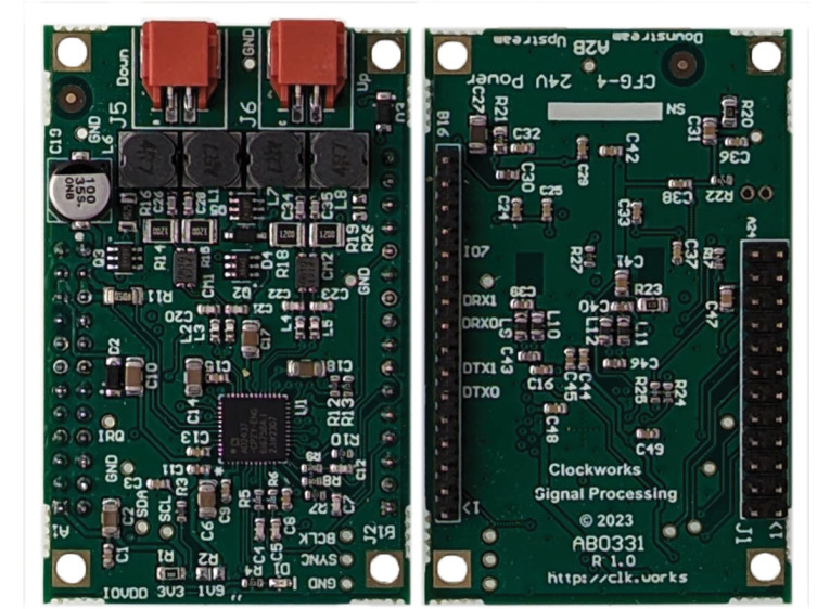
These modules use the same Molex 2 pin Duraclik connectors for A2B that Analog Devices has used on some of its EVM systems. These modules are intended to only be used with the same type of power system—feeding CFG4’s 24V in to a 9V CFG0 system would result in catastrophic failure. Analog Devices’ alternative CFG4 schemes, discussed in Part 2 of the article series, validates downstream nodes are of the same power type.
It is possible to mix AD2437 and AD2428 devices by isolating bus segments, the details depend on if you want to bridge power going from CFG4 to CFG0 powered segments. The simplest designs just have the first node in the new segment inject power, and the isolation consists of a transformer for galvanic isolation appropriate for the A2B bandwidth. It’s worth noting that individual nodes can also be galvanically isolated from the bus though there are more considerations if bus power is involved.
Summary
A2B technology continues to progress; compared to prior generation devices the features of the new AD2437 device provide an improved match to the needs of many audio applications. Here in Part 1, we introduced the feature set of the new AD2437 device and how it helps enable a range of audio applications. In the second part we’ll look at the details of two alternative CFG4 power schemes that Analog Devices has developed, along with a look at the new SigmaStudioPlus tools, development hardware, and some shipping end user audio products that incorporate A2B.
I asked Duncan Bosworth, Analog Devices’ VP for the Consumer BU, for his view of the future of A2B: “We are very excited about the future of A²B and our partner ecosystem continues to grow. We expect that the AD2437 transceiver will unlock new potential in professional audio and conferencing markets, supporting more immersive and higher fidelity experiences.” aX
Read Part 2 of this article: A2B Audio Bus: Two Alternative Power Schemes
Resources
Analog Devices A2B information:
Main A2B web page provides links to part information, tools, and related design information,
https://www.analog.com/en/solutions/a2b-audio-bus.html
Clockworks module information:
https://clk.works/products/a2b-products/a2b-module-selection-guide
B. LaMacchia, “Getting Started with Automotive Audio Bus,” audioXpress, four-part series, October 2020 to January 2021.
This article was originally published in audioXpress, July 2024