In an earlier installment (When Is a Regulator a Regulator?) we discussed source follower power supplies (aka Capacitance Multiplier) versus a regulating circuit. I used the example of a series regulator and we found that an actual regulator improves the stability and lowers noise and output impedance of the supply compared to a capacitance multiplier.
What I didn't mention is an alternative regulator topology to the series regulator: the shunt regulator. So, let’s look into that topology.
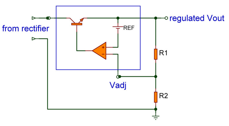
Figure 1 shows the basic series regulator, very similar to the one we previously discussed. Briefly, the op-amp drives its output (and thus the regulator output) until the op-amp input levels are equal. That fixes Vout to a value ((R2/R1)+1)*Vref. But as usual, the devil is in the details. How does it look on the system level, with a remote load powered by this regulator, as in Figure 2? We use an integrated regulator here, the ubiquitous LM317 series, which has the reference built in.
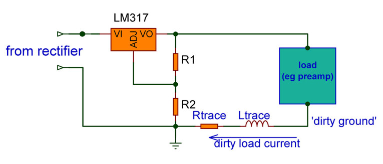
It is clear that while the regulator output between the top of R1 and the bottom of R2 is very clean and low noise, the power at the load is far from that! The dirty load current will carry components that are signal related, often strongly distorted especially in a Class (A)B amplifier stages. Wiring and PCB trace resistance and inductance will generate dirty voltage from the dirty current. It is easy to see that if your signal ground is connected to the same ground as that regulator, a distorted and noisy component will be riding on your signal reference; you may think that a few milliohms or nanohenries can be disregarded, but that’s not the case if you are aiming for -120dB THD+N!
There are a few possible remedies. You can give each (pre)amp section its own local series regulator, which can only solve part of the issue because you still have different “grounds” at different points. But there’s also a solution that keeps the “dirty load current” locally at the load stage so no distorted signal will be generated over any connecting line. Shunt regulators (Figure 3) to the rescue!
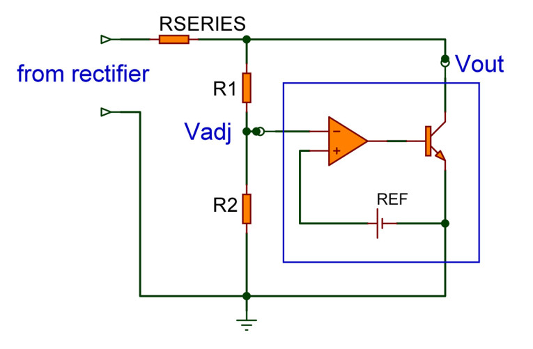
You can see why it is called a shunt regulator – the regulator now controls the output voltage by shorting or shunting the output voltage to some extent; if Vout gets too high, the load transistor is opened up to conduct more, and vice versa. An important element is the resistor RSERIES. The increased current shunted by the output transistor will cause Vout to drop, as it should, due to increased voltage drop across RSERIES. Neat, huh?
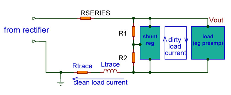
But how does this fix my dirty ground issue? Well, as is shown in Figure 4, that dirty current is now kept locally to the load and the shunt regulator. It no longer propagates through the system to contaminate signal grounds. Rtrace and Ltrace are still there but the current through them is clean, so no dirty voltages are generated. And you can place the shunt regulator very close to the load to keep the loop very tight.
There are two drawbacks to this solution. One, it requires separate shunt regulators at each stage of even parts of a stage for ultimate performance.
Second, it is inherently inefficient. The shunt regulator basically works by regulating the sum of the load current and the shunt current to remain constant (not entirely true but it is valid as a first approximation). Suppose we have a load that draws a current that can vary between 20mA and 80mA. At minimum load, the shunt has to absorb 60mA to keep the sum of shunt and load current constant. At maximum load the shunt current can be zero, but you probably don’t want to cut it that close. So, you’d set the shunt to say 100mA with no load. Then, if load current varies between 20mA and 80mA, shunt current varies between 80mA and 20mA.
You won’t use a shunt regulator for a high-power amplifier! But for ultimate performance goals, they are hard to beat. aX
This article was originally published in The Audio Voice newsletter, (#478), August 1, 2024.


