...when it regulates, you’d think. Yet, in many online fora and discussions you see circuits that “do something” with a power supply hailed as regulators even when there’s absolutely no regulation taking place. So, let’s peel it back.
The problem is simple: you have a “raw” power supply, such as from a mains transformer followed by a rectifier and reservoir cap on the one hand, and a nice circuit that wants a stable, noise- and ripple-free DC that doesn’t change with load or mains dips, on the other hand. It’s the thing in between we’re after.
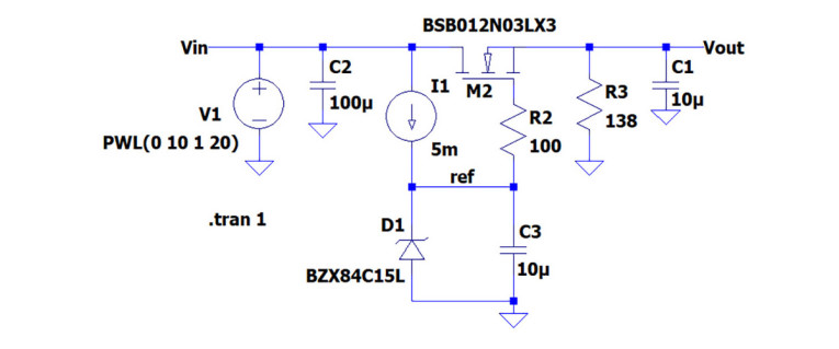
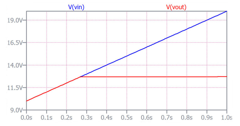
A clever solution is the so-called capacitance multiplier, as seen in Figure 1a. Because the M2 FET gate doesn’t take appreciable current, even with a moderate capacitance (C3) that gate voltage will be largely free of mains ripple, and so will the output voltage. The Zener diode, fed by a small current, will stabilize the gate (and thus output) voltage against changes in the mains voltage. The name “capacitance multiplier” comes from the fact that the output is much cleaner than you would expect based on the value of C3; it is as if the circuit multiplies the capacitor value with the gain of the FET. If we now ramp up the input voltage source from 10V to 20V, you see in Figure 1b that at about 13.8V the output indeed stabilizes at that level. So far so good.
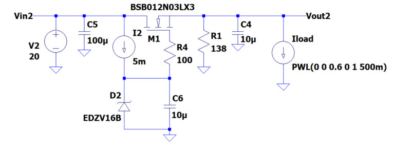
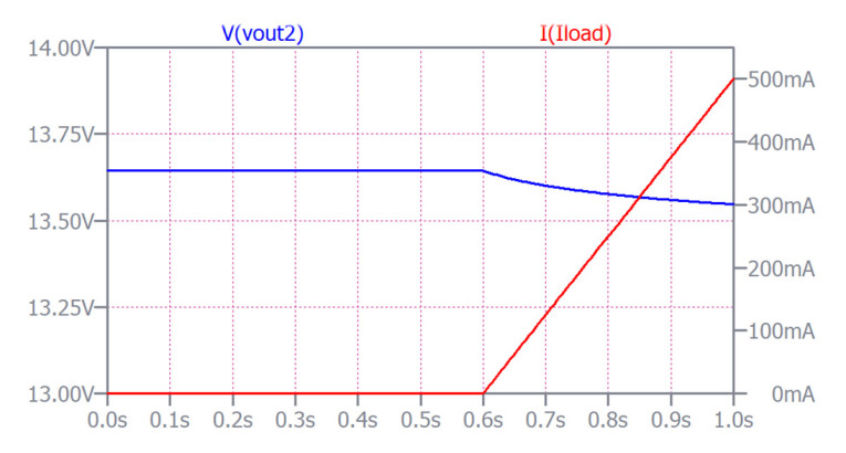
But what will happen when you vary the current drawn by the load? For the FET to be able to source more current, it needs more gate-to-source voltage as determined by its Gm (Gm being Is/Vgs). Since the gate voltage is constant, the only way more current is delivered is for the source voltage, the output voltage, to drop. In Figure 1c, I added a current source load I3 that increases from zero to 500mA DC after about 0.6ms into the simulation, and in Figure 1d you see that as the load current increases, the output voltage Vout2 starts to drop. EE101, and it is clear that nothing is being regulated. The output voltage drop is not much; about 100mV with a 500mA load change, but still. If the load is something like an audio amplifier, the current draw, and thus the output voltage, will vary with the signal, and you would see the audio on the supply voltage line. The impact on your sound will depend on the amplifier’s sensitivity to supply ripple.
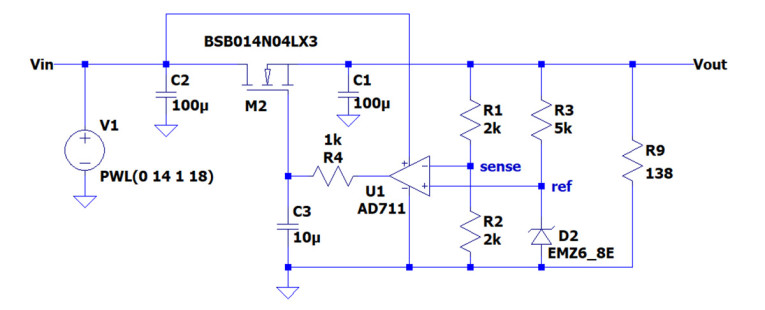
Now let’s get smart. What if we would take that unwanted variation in output voltage, invert it, and feed it back to the gate, in such a way that a drop in output voltage would cause a compensating rise in gate voltage? Whoa! – we’ve gotten ourselves a regulator. Figure 2a shows the basic scheme. We added op-amp U1 to the system. The non-inverting input (ref) receives a reference voltage generated by Zener D2. The inverting input (sense) receives a divided-down part of Vout.
It works as follows: assume that Vout drops so that the sense terminal drops below the ref terminal. The output of the op-amp will rise (sense is inverting input), M2’s Vg will rise and thus Vout will rise, and the sense voltage goes back up again. The opposite sequence happens if Vsense would rise above Vref. This way, the circuit regulates Vout to the set value.
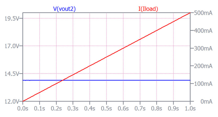
Figure 2b shows a similar picture as with the cap multiplier with the varying load added, but unlike for the cap multiplier, you see that Vout is rock stable despite the load current varying from 0 to 500mA - this is good! It all works in a continuous manner and the upshot is that Vout stabilizes at a value for which Vsense = Vref no matter what the load current is (within limits of course). The ratio of R1 to R2 determines the Vout value, and with the equal resistor values Vout = 2*Vsense.
Because the op-amp has such high gain, any minuscule change in Vout will immediately change M2’s Vg to counter it. So, even with large load current changes, Vout stays pretty constant. The rate at which Vout drops with load current change is measured as Rout (which is Vout/Iload according to Mr. Ohm) and good regulators can have Rout in the single milliohm range, meaning that a load current change of 1A only changes Vout by a few millivolts.
Another important metric is how well a regulator suppresses the noise and mains ripple in the input voltage: the power supply ripple rejection (PSRR), and good ones can suppress that junk 100,000 times (100dB) in the audio frequency range.
You don’t really have to build something like the device shown in Figure 2 as semiconductor manufacturers have integrated the whole thing except the electrolytic capacitors in integrated circuits, such as the LM78xx series of ICs. Just three pins: input, ground, and output; add some electrolytics, and you’re done. Some can be set for different output voltages with a pair of resistors, such as the LM317 series.
In recent years, new integrated voltage regulators have been designed, spurred on by automotive and cellphone applications, that are close to perfection. They have a PSRR of up to 70dB or 80dB (3,000 to 10,000) up to 100MHz! They only need a few 100mV between input and output voltage, which is important: the quantity (load current) x (Vin-Vout difference) is power, in Watts, dissipated as heat loss in the regulator. You don’t want a lot of that in your cell phone, and it would also be a waste drain on your battery. aX
Note: the images included in this article are of simplified circuits to illustrate behavior, but for a real regulator some additional parts would be required. Also, the unmentioned assumption is that Vin and Vout are positive voltages - this is a positive voltage regulator. But it is easy to see that by changing device polarities you could also build a negative voltage regulator on the same concept.
The content here pertains to linear regulators. If we need medium- and high-power regulators where the losses need to be absolutely minimized, we may look at switching regulators. Another kettle of fish, which we can investigate another time.
This article was originally published in The Audio Voice newsletter, (#463), April 4, 2024.


