The Small Signal Picture
There is a fundamental difference between bandwidth and slew rate. The reason lies in the definition: bandwidth is a small signal parameter. If you ask a simulator like LTspice to calculate frequency response, it linearizes all active devices at their operating point, applies the input signal, then calculates gain and/or attenuation in the circuit.
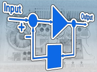
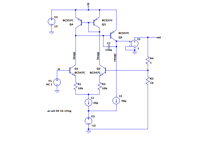
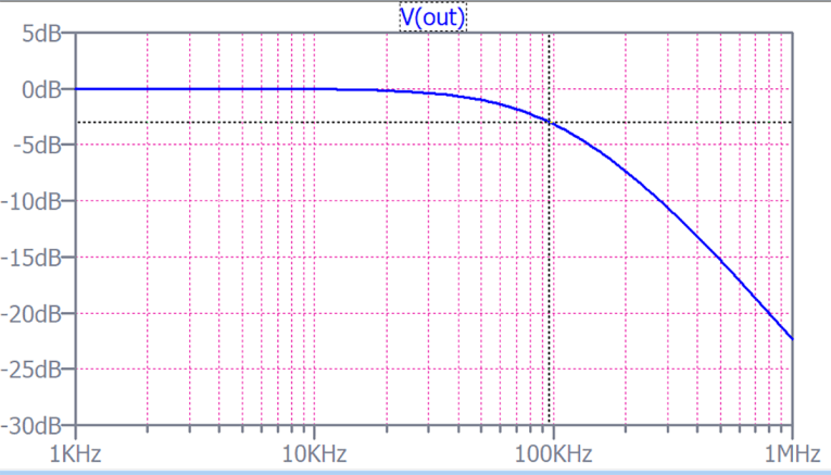
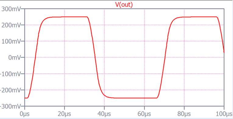
Let us take an example, as in figure 1. This is an opamp-like structure of a differential input stage, (Q1, Q2), a gain stage (Q5) and an output buffer E1. There’s 100% feedback so we expect a gain of one. Let us do a response graph, as in figure 2. Looks good, DC coupled with a 3dB frequency of ~95kHz. We can do a quick check with a square wave and as figure 3 shows, nothing to worry about. Done.
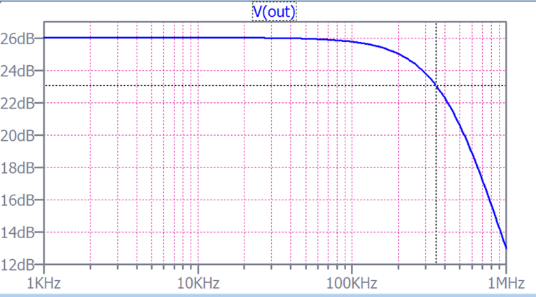
Well, not quite. Look at the input signal source, it says "AC 1" (Figure 1). LTspice is instructed to use a 1V AC input signal in the calculations. What happens if we use, say, "AC 20"? We know this won’t work – a circuit with +/-15V supply can't process a 20V signal. But figure 4 shows otherwise: the circuit seems to be quite happy processing a 20V signal (a +26dB level)! Remember, the simulation calculations assume that all active devices are linear about the operating point so the actual signal level doesn't make any difference! It would work equally well if we specified Vin as 1Megavolt.
The Large Signal Picture
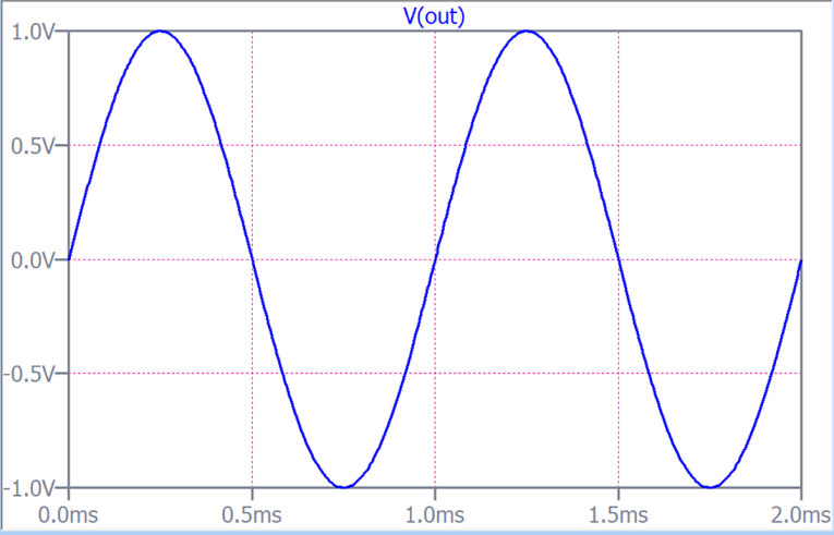
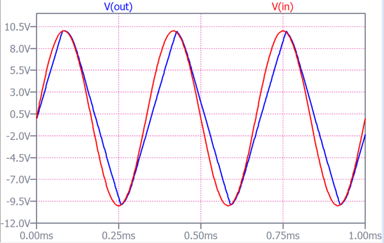
Simulating with unrealistically linear devices have value as seen above, but we also need to know how out circuit handles large signals, with the non-linearities of the active devices considered; that’s how it is in the real world. In the simulation world, you’d use what is known as Transient Response analysis. We run one with the input signal set to 1V at 1kHz and figure 5 shows the result, and it is what we expect, a nice, undistorted output with 1V amplitude. But now we are using the large signal non-linear models of the active devices so what happens at the 10V input level? At 1kHz, we still see a nice 10V sine wave output, so let's up the frequency. At 3kHz we see figure 6. Whoa – what’s that??
That, my friend, is slew rate limiting. I overlaid the input sine wave (red) with the output signal (blue). What is apparent is that the blue output cannot keep up with the input signal. It "slews" along a straight line as if something is limiting the maximum rate of rise or fall. And that is indeed the case, and the culprit is that innocent looking capacitor C1 between C and B of gain transistor Q5. That capacitor is needed to compensate the amplifier, to make sure the gain is less than 1 at the frequency where the output phase shift reaches 180 degrees.
At 180 degrees phase shift negative feedback is turned into positive feedback and if there would still be gain at that point, we would have an oscillator instead of an amplifier. But for the gain stage output to be able to deliver the 10V output signal, the collector side of C1 must also follow that + / – 10V signal swing.
Which means that C1 needs to be repeatedly charged and discharged as the signal goes through the full amplitude swing. And, ultimately, that charge/discharge current comes from the collector of Q1. And the current from that point can’t get any higher than 20uA for that is the I1 tail current of the input stage, so even with all current diverted to Q1, it is limited to 20uA, a constant current! That is the reason why you see a straight blue output line in figure 6: it is the constant current limited charging of C1 from current source I1.
Let us verify that by lowering the C1 value, so it can charge/discharge faster with that 20uA tail current. With C1 at 50pF the output again looks like a perfect sinewave (not shown). But there will always be slew rate limiting if you go high enough in frequency or signal level.
The Bottom Line
It doesn’t really matter whether you do these measurements in a simulator or on a real amp, the results will be very close. But the take-away is that a good-looking frequency response and a nice square wave response is no guarantee for a good high frequency performance with high output levels. You must check the performance not only at the maximum audio frequency, but also at the maximum output level at that frequency. Preferably with a distortion analyzer, because the onset of slew rate limiting will be very clear as quickly rising distortion.
The second take-away is that compensation for stability, bandwidth and high level high frequency performance are all related, and that is where a competent designer makes his living.
|
This article was originally published in The Audio Voice newsletter, (#443), October 19, 2023.