Yes, it can be hard to get your head around feedback. We see a circuit where a forward signal passes though some devices and passive parts that all cause phase shifts and distortions and then part of it is fed back to the input side and summed with the input signal, and we expect it gets there in time to correct the errors before they get created?
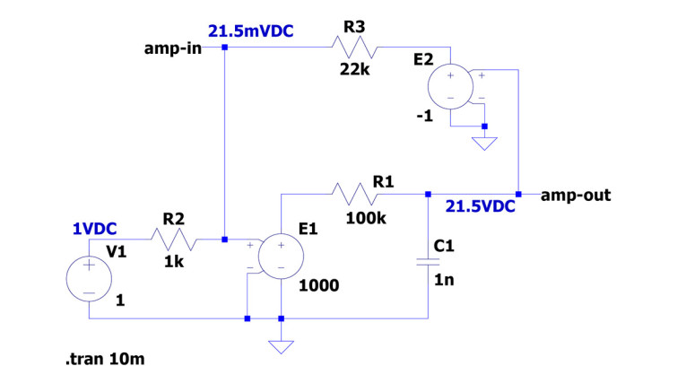
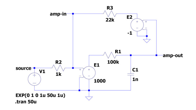
For a good illustration of the workings, I need a situation where we clearly see how the feedback corrects deviations from the desired output in real time, so to speak. Figure 1 above shows the circuit diagram. Let’s set the scene with a DC input signal of 1V. The amplifier has a gain of 1000 and rolls of at about 1.6kHz. The output signal is inverted by E2 before being sent to the feedback loop, to maintain negative feedback.
The nominal gain from R3/R2 would be 22k/1k = 22 times with an infinite open loop amplifier gain (E1). E1 only has a gain of 1000 though, so the closed loop gain will fall short of 22. LTspice tells me V(amp-out) = 21.5V. The amplifier input signal V(amp-in), which in the infinite open loop case would be zero, turns out to be 21.5mV DC. And that squares beautifully: that 21.5mV amplified 1000 times by E1 gives an output of 21.5V, which is indeed what we measure. But this is steady state – how about fast-moving signals or music?
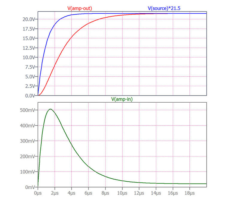
Figure 2a shows the circuit of Figure 1, but with a modified input signal: a fast pulse exceeding the capabilities of the amplifier: the input pulse rise and fall times are shorter than the amplifier rise and fall times. Figure 2b shows the inputs and outputs. In the top pane of Figure 2b the red curve is V(amp-out), while the blue curve is Vsource x 21.5 (remember, 21.5 is the circuit gain). Ideally, the curves would overlap; V(amp-out) would be exactly Vsource x 21.5. And a bit down the line, they do. But the source rises faster than the amp can follow so there’s a deficit in V(amp-out) for the first dozen microseconds.
During the initial period, with V(amp-out) a bit too low, the voltage across R3 is a bit too high (Figure 2a). That means that the junction between R3 and R2 is a bit higher, which means the input to amplifier E1 is a bit higher, and that is beautifully shown by the green curve in the lower pane of Figure 2b. The input to the amplifier rises in response to the lagging output, to around 500mV at its maximum. Remember, in steady state with DC, that V(amp-input) was just 21.5mV; and down the line, after a few tens of microseconds, V(amp-out) gets to 21.5V and V(amp-in) gets to 21.5mV. Through feedback resistor R3, the deficit in V(amp-out) causes a rise in V(amp-in) which makes up, partially, for some of the output shortfall, although it doesn’t so completely. The feedback cannot totally cancel or compensate for the error – there still is a shortfall in V(amp-out) during the fast rise of the input.
So, What Did the Feedback Give Us?
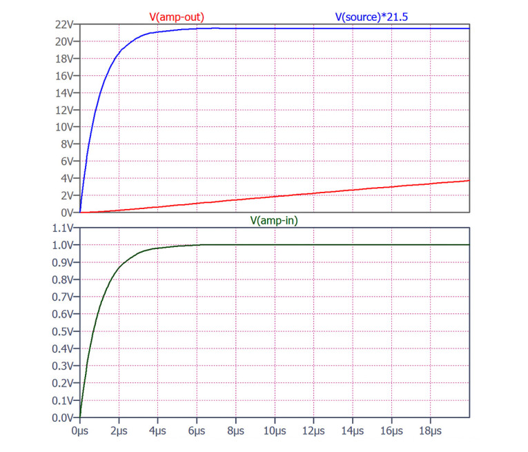
Suppose we would have built an amp with a gain of 21.5 and no feedback, by taking R3 out of the circuit of Figure 2a and setting E1 to 21.5. The output signal is now as shown in Figure 3a, which has the same time scale as Figure 2 and it is very slow to rise towards the expected value. Figure 3b expands the scale twenty times, and yes, eventually V(amp-out) gets to 21.5V, but it takes ages without the help of feedback!
I illustrated the workings of this circuit with a fast-rising pulse, but the exact same reasoning is valid for a signal that is distorted internally in the amplifier. For example, with some third-harmonic distortion, the amplifier output positive peak might be a bit too high, and the negative peak a bit too low (or vice versa) in amplitude. Same difference – the output voltage deviates from the target, and the feedback divider causes a change in V(amp-in) to counter the error. And the error is not nulled, but decreased by an amount determined by how strong the feedback is, which ultimately depends on how much larger the E1 gain is than the target gain. Any deviation in V(amp-out) from the wanted value, whether it is due to distortion or inability to follow a fast signal, is called the error. Feedback decreases the error but cannot null it.
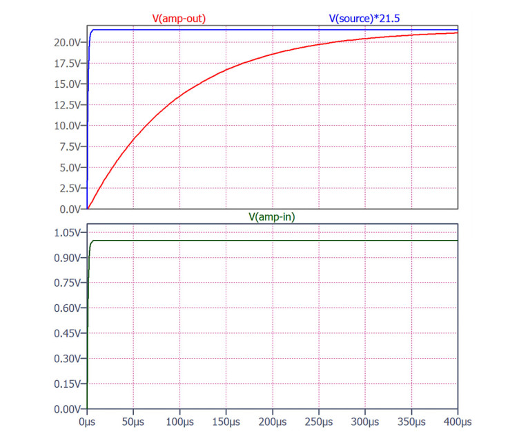
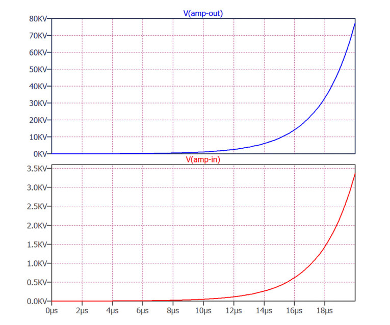
I used a separate inverting stage (E2) to make sure the feedback signal is negative with respect to the output signal. In a real amplifier you cannot maintain perfect inversion from DC to lightspeed. Eventually, phase shift will cause the feedback signal to become in phase with the output signal, and the correction applied to the amp input will be the wrong polarity. We then have a positive feedback amplifier, and the result can be seen in Figure 4. V(amp-out) increases, which increases V(amp-in), which increases V(amp-out), ad infinitum.
Those voltage scales in Figure 4 are not realistic; in a practical amplifier the output will be limited by the supply voltage, and depending on conditions, the output will slam to a rail or start to oscillate at a frequency determined by the circuit time constant(s). And before the feedback has turned fully positive, you will already start to see overshoots on the input and output signals as the amplifier becomes increasingly unstable.
The Verdict
As long as the feedback signal remains negative in polarity, it has a clear beneficial effect on the performance of the complete amplifier. And there are many more beneficial effects I have not mentioned. A gain variation of 10% of the 21.5 times gain of the non-feedback amplifier will immediately have the same 10% variation in the total circuit gain. In contrast, a 10% variation in the gain of the x1000 amplifier in the feedback circuit will only have a 0.23% variation in the circuit gain.
There’s much more, but not enough space here to keep going. Negative feedback cannot make things perfect, and sometimes turns your amplifier into an oscillator. But it is not something that comes too late to correct what has already happened. It’s a tool, and as every craftsman knows, tools must be learned and their limits understood before they can be applied to their advantage.
Comments and contributions are always welcome.
techeditor@audioxpress.com
This article was originally published in The Audio Voice newsletter, (#434), August 24, 2023.