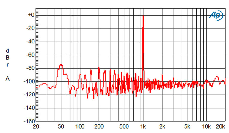
But look at the left side of the graph, at the region at and just above the mains frequency. The spikes at the mains frequency and the harmonics caused by the rectification process are higher than the distortion. Hum and buzz components that swamp the harmonic distortion, leaving you with the question, why bother with the harmonics? Even switched-mode power supplies (SMPS) can have non-negligible mains related spurs in the audio band. Some of those unwanted signals come from radiated fields, but most are from non-optimal grounding. Let’s explore that a bit.

The key to understanding grounding issues is to get away from the idea that circuit nodes have “a voltage.” Hint: voltmeters always have two probes [1]. And no, the second probe is not meant to ground the meter for safety – the second probe provides the reference against which the first probe measures the voltage.
Normally we measure voltages against ground – but how do we measure the hum and noise on ground then? The way out is to realize that there isn’t “a” ground. Ground is a net, consisting of several nodes and interconnecting wiring and PCB traces and often chassis sections. And all those connections exhibit resistance, inductance, and parasitic capacitance. Wiring between two points causes a current through the wiring (otherwise there would be no need for the wire) so different points on a wire net carry different voltages and ground wiring is no exception.
Hmmm. If all those points in the ground net can have different voltages, what is the real ground then? Answer: none of the above. Or better yet: ground is what you call it. It is a reference.
Grounding the Ground
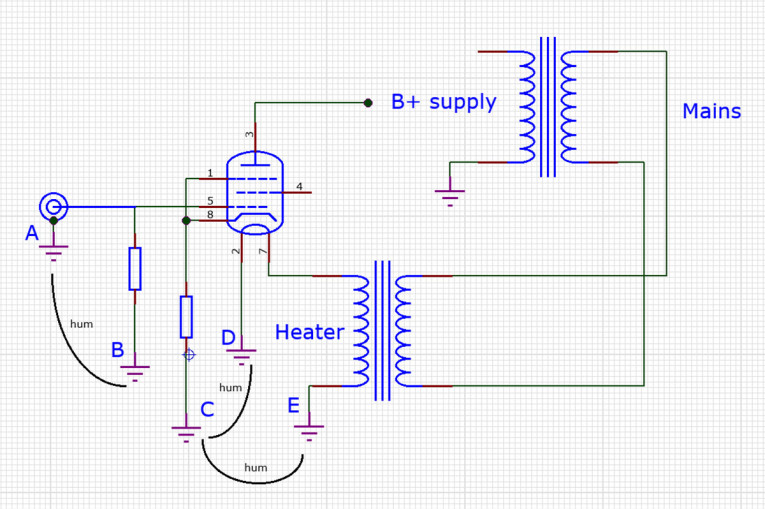
Let us start at the beginning. The input to a power amplifier (assuming RCA/Phono) is a signal wire and a ground wire. Assuming the signal source is perfect, if we measure that signal against its RCA ground wire A we measure a perfect signal. We want this signal to go to the amplifier input as-is and come out amplified in voltage or current but not altered in any other way.
But what is the signal that gets to the amplifier input? Look at Figure 2. The amplifier input signal is the signal between the grid and the cathode, Vgk. And that would be exactly the input signal, if all the ground points A through E had the same voltage – and there lies the rub! As an example, say the heater return current flows between point D and E, connected by some wire and/or a section of chassis - that can cause a hum voltage between those points because of the impedance/resistance between them. So, if, for example, point A would be connected to point B, and point C and D would be connected at point E (a common situation), and there’s some wire and/or a section of chassis between points B and E, you are almost guaranteed a hum voltage between grid and cathode and hum will come out of the speaker. (I am glossing over the issue of Protective Earth (PE) connection, which can complicate the whole thing).
One Solution
While it is usually not possible to get a perfect solution, you can do a lot to mitigate the problems. Make sure that sensitive input grounds are all directly connected and not share wiring or a chassis section with other (large) currents. In Figure 2, directly connect pins A, B, C and D to some point, so you are certain that their grounds are all the same. Then, if there is some resistance between that common point and point E somewhere else, the effect is only that the heater voltage has some disturbance on it, but it is unlikely to be audible.
A very good treatise on this subject has been written by Merlin Blencowe aka The Valve Wizard [2]. Focused on tube circuits but equally applicable to solid state and hybrids – it’s the concept that counts! See for instance Figure 3, taken from his book Designing Valve Preamps for Guitar and Bass (ignore the input ground caps and the hum-loop block for the moment).
The high current grounds from the speaker load and the power supply are returned to the same ground point A. We declare this the ground. The low current/signal grounds from the source and stages C, B, E, and D are also returned to this same point. So, point A is the common ground for all signals in the system, and if you want to do clean measurements, measuring the outputs of the pre-stages or the final output, or the power supply points in the amp, hang your meter ground probe at point A.
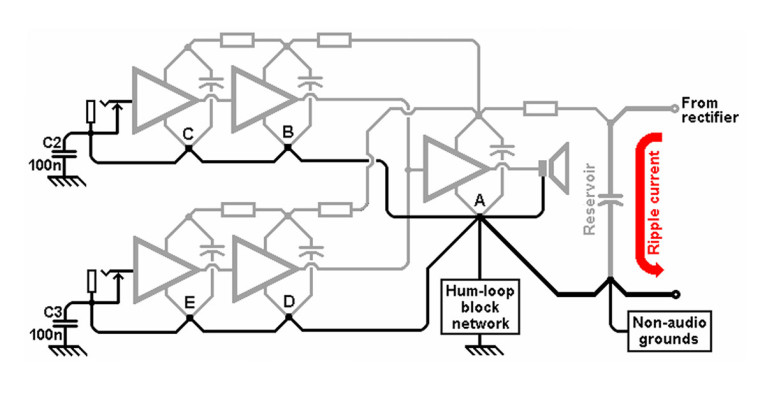
The astute reader might comment that the supply return currents for block C and E flow through the return wiring of block B and E and thus may set up a disturbance voltage across those wires that appears in series with the signal for blocks C and E. And they would be perfectly right.
If you want to follow this through consequently, each of the blocks C, B, D, E would have separate ground returns to point A. But audio design is always a matter of compromise: the return grounds from the pre-stages carry relatively small currents and running separate grounds would add to the construction complexity. If taking care of the high current wiring from power stage and power supply gets the disturbances below audible level, your mission has succeeded. aX
References
[1] B. Putzeys, “The G-word, or how to get your audio off the Ground”
[2] M. Blencowe, Designing Valve Preamps for Guitar and Bass, Chapter 15, www.valvewizard.co.uk/Grounding.pdf
This article was originally published in The Audio Voice newsletter, (#492), November 14, 2024.


