The reason is clearly that it’s quite a jump to throw the Thiele-Small (T-S) parameters overboard and at the same time advance your skills in box modeling sufficiently to actually achieve an improvement. The authors have advocated for some years to improve the simulation of loudspeakers with advanced parameters. We have published the relevant theoretical details and overcome certain obstacles; most notably, how to measure the viscoelasticity without expensive equipment, and how to work with the advanced model in the time domain.
Speakerbench: A Free Web-App for the Community
The first step in our proposed modeling workflow is to compute the advanced model parameter set, and for this purpose we created the Dual-Added-Mass procedure. The details of this procedure are described in a recent AES article [2]. The approach is verified to be capable of determining Bl within 1.0% and MMS within 2%. In particular, the viscoelastic beta parameter, as well as the advanced electrical parameters, are extracted from the measured data.
The procedure offers a formal sanity-check for the measurement quality, unlike the classical added-mass method for which seasoned engineers would normally rely on experience and intuition (i.e., a gut feeling) to assess the quality of the extracted model parameters. Although the dual-added-mass procedure has been well-documented, it is non-trivial to design an algorithm to robustly carry out the parameter fitting and make an objective error estimate.
Thus, to facilitate use and adoption of the advanced model, we have created a web-application named Speakerbench, available online at speakerbench.com. The user must only perform three impedance measurements with suitable equipment, and Speakerbench does the rest. The transducer data from the app is provided in a compact JSON (JavaScript Object Notation), a lightweight data-interchange format, and can be downloaded and shared across the globe. Unlike DLC Dumax, LinearX, and Klippel data, the results from Speakerbench are valid only in the small-signal domain, but the data is of high quality and suitable for box design. After the advanced parameters are computed, the user can carry out box simulations within Speakerbench, or export to dedicated design software (e.g., VituixCAD).
Steps in Creating an Advanced Transducer Model and Datasheet
The key requirements for a good result with Speakerbench are that you have a sufficiently accurate setup for impedance measurements, and a quality scale for measuring the added masses. Measuring impedance should either be executed with a stepped-sine where each measurement is allowed to stabilize, or alternatively in a slow sweep (say minimum 10 seconds and preferably with a sweep profile that gives you more time at the lower frequencies). Measuring with 0.1 gram precision is mandatory for normal transducers with MMS in the 10-25 grams range.
Let’s walk through the process. Assemble four masses (using, for instance, a combination of Blu Tack and nuts) to be added to the diaphragm of the transducer. We recommend that total mass, which we denote by m2, be close to the moving mass of the driver. This is just a guideline and not essential.
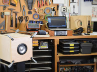
1: Attach the four masses, distributing them evenly near the voice coil (or just outside the area where the dust cap is attached) to ensure the load is balanced evenly avoiding rocking modes, as illustrated by the Photo 1a.
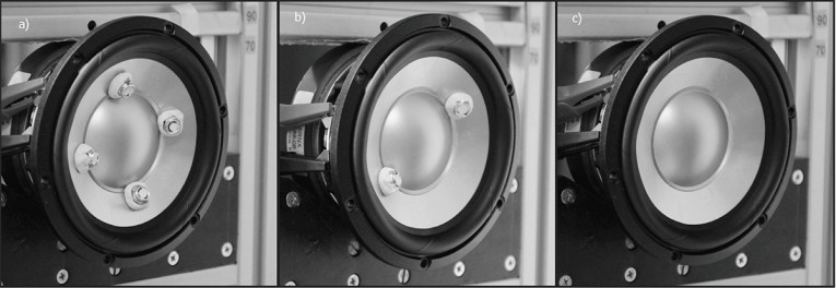
2: Measure the impedance of the transducer in free air, with all four pieces attached to the cone (Photo 1a). This is the m2 impedance measurement.
3: Gently remove two diagonal pieces such that about half the added mass remains on the cone (Photo 1b). Remeasure the impedance with the remaining mass (m1) on the cone. For reference, weigh the removed mass (m2 - m1) on a precision scale. When you remove the masses, avoid moving the cone (it should remain in its rest position).
4: Gently remove the remaining two masses (Photo 1c) and remeasure impedance. This is the unweighted measurement. Weigh the removed mass (m1) on a precision scale. Sum the two weight measurements to calculate the total mass, m2.
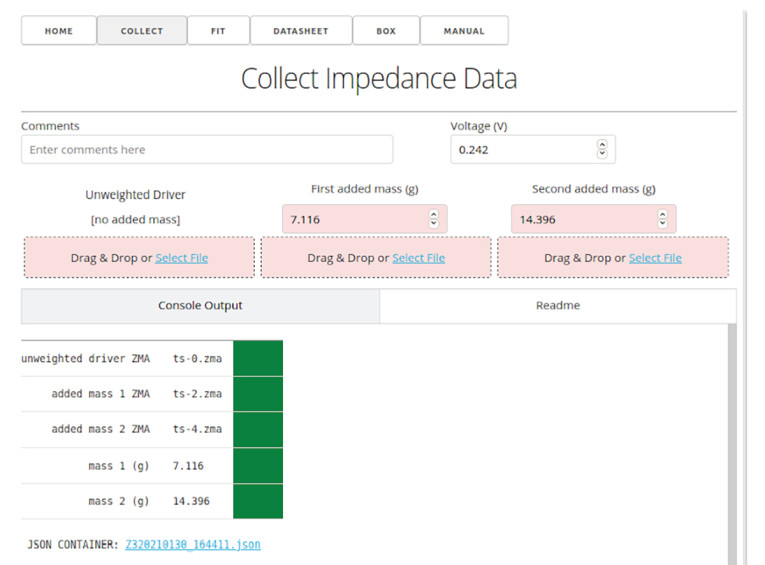
5: Upload the three impedance measurements and the weight of the masses (m2 and m1) into the COLLECT app (Figure 1), then download the resulting JSON Z-file.
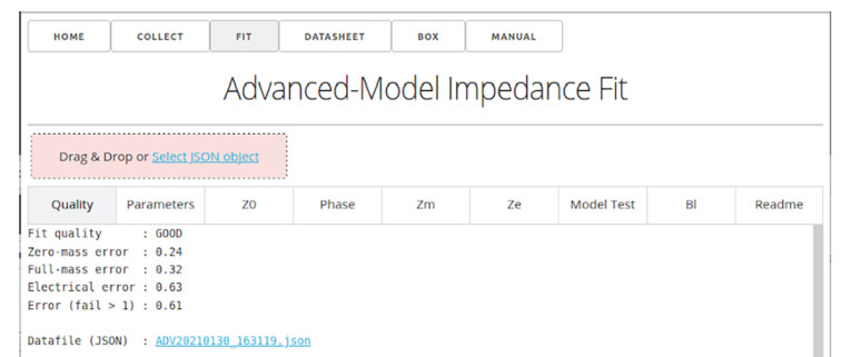
6: Upload the Z-file from Step 5 into the FIT app (Figure 2). Speakerbench will then compute the advanced model parameters, as well as a quality-of-fit metric that can be assessed in the resulting plot windows. The advanced parameters are provided in a downloadable JSON ADV-file.
7: Upload the ADV-file into the DATASHEET app (Figure 3). Here you simply add a description of the driver you’ve measured and a few important parameters, like SD and maybe XMAX, and the datasheet is then complete, provided in a downloadable JSON SBD-file.

Quality Assessment
By performing three impedance measurements instead of two (as in the classic added-mass method), the pure motional impedance can be extracted with a minimum of model assumptions. From this pure motional impedance, the viscoelastic beta parameter is then determined. The remaining blocked-electrical impedance can be derived by a relatively simple yet powerful set of algebraic operations.
As part of the analysis, the algorithm attempts to extract a stable value of Bl over a region of about one octave around the resonant frequency. This gives a useful indication of the robustness of the overall fit.
After the fitting procedure is complete (Step 6) the fit quality is automatically assessed. In the Quality tab of the FIT app, a fit rating is provided (Figure 2). This means you don’t have to be an expert in analyzing the output from the fitter. Possible ratings are (1) EXCELLENT, (2) GOOD, (3) FAIR, and (4) FAIL. Beyond these simple ratings, the user can also study the graphs in the succeeding tabs, where the app provides plots of the motional impedance (ZM), the blocked-electrical impedance (ZE), a model test that essentially compares your three measurements with the simulations based on the established model parameters, and Bl over the fit range.
To get an excellent rating probably requires some experimentation and building experience with the added mass approach. Once you can achieve an excellent rating, it’s worth celebrating (with a beer or other beverage). The good rating is also sufficient for reasonably accurate box simulations. The Speakerbench article in the 2020 Loudspeaker Industry Sourcebook [3] provides more information.
Box Simulations with Speakerbench
Speakerbench wasn’t initially intended to do box simulations, but there were numerous motivations to offer this functionality. Once an SBD file is created or uploaded, the transducer parameters are automatically forwarded into the BOX app (Figure 4), and an initial (probably bad) proposal for a box is provided. Just push the BOX button at the top. You can then explore the Settings to find an optimal configuration.

JSON Format and Portability
Speakerbench makes use of JSON as a standard container for calculation and datasheet output. This way you can easily share datasheets and simulations with fellow speaker designers. An online database of datasheets (SBD files) could easily be deployed, if desired. If someone sends you a Z-file or ADV-file or SBD-file, you can download it to your smartphone and then drop it into Speakerbench running on a browser.
Why Speakerbench?
What makes Speakerbench unique is that high-quality transducer data can be ensured even for the DIY speaker builder. The improvement in accuracy with the advanced model can be readily achieved, and should prove useful particularly when quantifying the various box losses. The user should be able to easily and accurately determine a suitable box volume. Speaker designers (DIYers or professionals) rarely build more than one box to determine the optimal volume for a loudspeaker system. With that one prototype box, you just have to make things work. This explains why it is so important to determine the best box volume from the very beginning.
Moreover, Speakerbench is a web-app and works on any computer, tablet, or smartphone with a browser without any software installation required. The online version will always be up-to-date with the latest one we have made available. Speakerbench collects the research and the proposed methods into an easily accessible software suite. We do the software development, as well as the underlying research and modeling, to help the industry move forward and improve their methods.
It is our hope that Speakerbench will facilitate the jump from legacy Thiele-Small parameters to more advanced modeling, and that people will feel like giving it a chance. A brief manual is available on the https://speakerbench.com website, and in addition we have created a series of short tutorial videos available on YouTube (a link is provided in the online manual). aX
This article was originally published in audioXpress, September 2021.
Read the first part of this article here: Parameter Estimation and Box Simulation with Speakerbench (Part 1) - Model Parameter Comparisons
References
[1] C. Futtrup, “Losses in Loudspeaker Enclosures,” Audio Engineering Society (AES) Convention: 130 (May 2011), Paper Number: 8324, Publication Date: May 13, 2011. www.aes.org/e-lib/browse.cfm?elib=15791
[2] J. Candy and C. Futtrup, “An Added-Mass Measurement Technique for Transducer Parameter Estimation,” Journal of the Audio Engineering Society (JAES), Volume 65, Issue 12, pp. 1005-1016; December 2017.
www.aes.org/e-lib/browse.cfm?elib=19366
[3] C. Futtrup and J. Candy, “Speakerbench,” Loudspeaker Industry Sourcebook (LIS) 2020, page 124-131.
www.loudspeakerindustrysourcebook.com/articles/speakerbench
 About the Authors
Claus Futtrup received his MSc in ME from Aalborg University in 1997 and has worked in the loudspeaker industry ever since. From 1997 to 2006, he worked at Dynaudio A/S first as an R&D Engineer, designing loudspeaker boxes and later as a System Engineer for automotive. From 2006 through 2007, Claus was employed as a Transducer Design Engineer at Tymphany in Denmark and in 2008-2013 he was R&D Manager at Scan-Speak. From 2013 to 2015 he worked as Technical Sales Manager for SEAS, Norway, and in 2015 he was promoted to Chief Technical Officer. From August 2021, Claus moved back to Denmark and started working at DALI as manager of the acoustics team.
 Jeff Candy was born in Edmonton, Canada in 1966. He received his Ph.D. in Physics from the University of California, San Diego in 1994, and is currently Director of the Theory and Computational Sciences Group at General Atomics in San Diego, CA. He works primarily on theoretical and computational plasma physics, with focus on plasma kinetic theory and turbulence. In the field of audio, he is interested in the application of theoretical acoustics to practical situations. Jeff is a member of the Audio Engineering Society (AES) and a fellow of the American Physical Society (APS). In 2003, he received the Rosenbluth Award for fusion theory, and was 2008 Jubileum Professor at Chalmers University.