Self-Bias Emitter Circuit
Patent Number: 9,332,344
Inventor(s): Stephen Wood (Poway, CA),Elwood Norris (Poway, CA)
Assignee: Turtle Beach Corp. (San Diego, CA)
Filed: May 22, 2015
Current CPC Class: H04R 3/00 (20130101)
Granted: May 3, 2016
Number of Claims: 19
Number of Drawings: 11
Abstract from Patent
An emitter circuit for providing a bias voltage is disclosed. The emitter circuit can comprise an emitter. The emitter circuit can comprise a transducer that includes a primary winding and a secondary winding. The secondary winding can be operable to receive an alternating current (AC) carrier signal. The emitter circuit can comprise a voltage multiplier operable to receive the AC carrier signal from the secondary winding and generate a DC bias voltage. The emitter circuit can comprise a Zener diode to limit amplitude of the DC bias voltage applied across the emitter. The emitter circuit can comprise a filter capacitor operable to smooth the DC bias voltage applied across the emitter.
Independent Claims
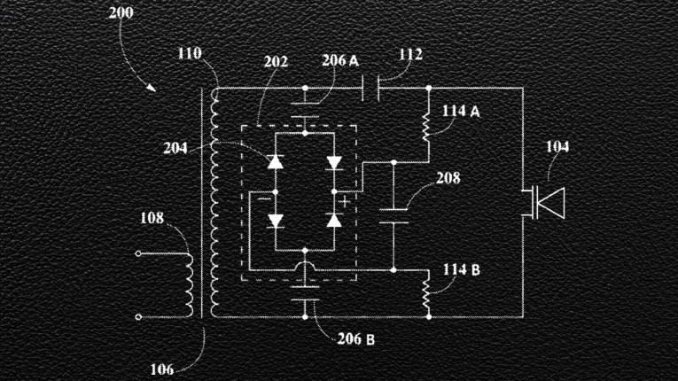
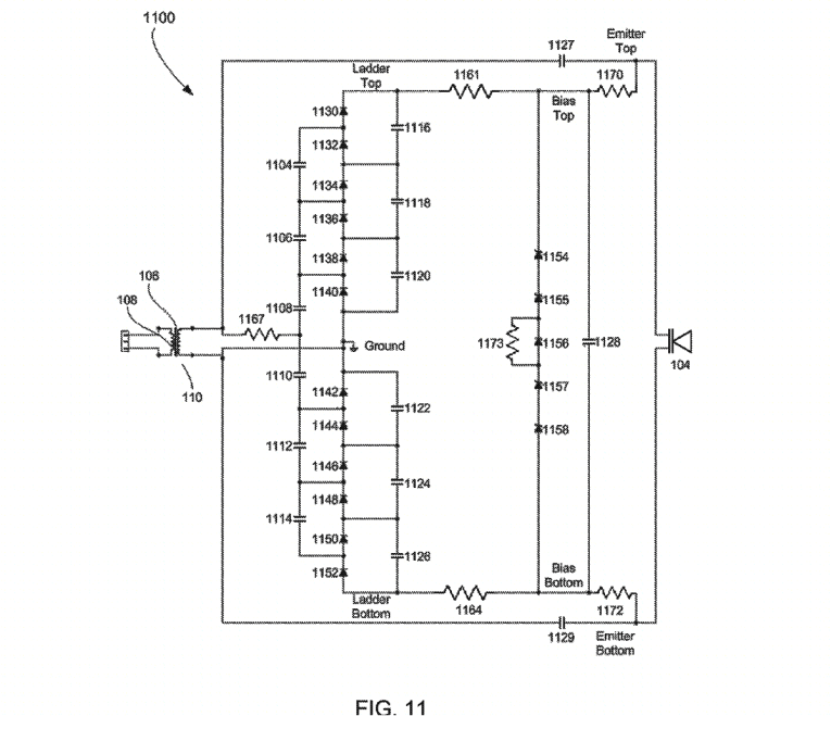
1. An emitter circuit for providing a direct current (DC) bias voltage, comprising: an emitter; a transducer that includes a primary winding and a secondary winding, wherein the secondary winding is operable to receive an alternating current (AC) carrier signal; a first voltage multiplier and rectifier operable to generate a positive DC bias voltage from the AC carrier signal; a second voltage multiplier and rectifier operable to generate a negative DC bias voltage from the AC carrier signal, wherein the second voltage multiplier and rectifier is symmetrical to the first voltage multiplier and rectifier; one or more Zener diodes operable to limit an amplitude of a DC bias voltage applied across the emitter, wherein the DC bias voltage is based on the positive DC bias voltage and the negative DC bias voltage; and a filter capacitor, in parallel with the one or more Zener diodes, operable to smooth the DC bias voltage that is applied across the emitter.
9. An emitter circuit in a parametric loudspeaker for providing a bias voltage, the emitter circuit comprising: an emitter configured to emit ultrasonic signals; a transducer that includes a primary winding and a secondary winding, wherein the secondary winding is operable to receive an alternating current (AC) carrier signal; a voltage multiplier and rectifier operable to generate a DC bias voltage from the AC carrier signal; a Zener diode operable to limit an amplitude of the DC bias voltage that is applied across the emitter; and a filter capacitor, in parallel with the Zener diode, operable to smooth the DC bias voltage applied across the emitter.
16. An emitter circuit in a parametric speaker for providing a bias voltage, the emitter circuit comprising: an emitter configured to emit ultrasonic signals; a transductor that includes a primary winding and a secondary winding, wherein the secondary winding is operable to receive an alternating current (AC) carrier signal; a voltage multiplier operable to receive the AC carrier signal from the secondary winding and generate a DC bias voltage; a Zener diode to limit an amplitude of the DC bias voltage applied that is across the emitter; and a filter capacitor operable to smooth the DC bias voltage applied across the emitter.
Reviewer Comments
Even in 1925, when young engineers Chester W. Rice and Edward W. Kellogg of General Electric, were developing the first moving coil loudspeaker, as disclosed in their seminal paper in 1925, “Notes on the Development of a New Type of Hornless Loudspeaker,” in the Transactions of the American Institute of Electrical Engineers, they were already well along in the parallel development of the electrostatic loudspeaker, for which Edward Kellogg was granted US Patent 1, 983,377; “Production of Sound.”
Unfortunately, the diaphragm of choice at the time was pig intestine gilded with conductive gold sheathing, which was known for its short lifespan, among other limitations. It wasn’t until the advent of the first polyester thin films in the late 1940s and development of the high tensile strength versions in 1952, dubbed Mylar, that a practical diaphragm was available that inspired a new wave of electrostatic loudspeakers, with two of the most notable examples being that of Peter Walker’s QUAD ESL from England and Arthur Janszen’s electrostatic panels, which he developed into the Model 9 for KLH in the US.
While the electrostatic loudspeaker embodied a number of desirable “quality” performance attributes it also had significant “quantitative” limitations, such as size requirements and sound pressure level (SPL) limits for a given surface area, which kept it from being a dominating technology. It also had an additional issue that many found to be a limitation for total acceptance in the domestic environment.
Even though powered loudspeakers have become quite common of late, up until recently, AC power cords to loudspeakers were a frowned upon nuisance and were generally avoided. But, electrostatic loudspeakers have a requirement for a source of low current, high voltage DC charge, so plugging them into the closest power outlet has been a necessity.
One of the earliest attempts to make large format electrostatics more practical in this regard was developed by the electrostatic headphone manufacturer, Koss, when it brought its first electrostatic loudspeaker to the market. The Koss Model One, based on US Patent 3,992,585, “Self-energizing electrostatic loudspeaker system” by inventors Jacob Turner and Robert Grodinsky, used an onboard battery with a basic DC-to-DC convertor to raise the battery voltage up to the levels required for biasing the electrostatic panel. In a preferred embodiment of the Koss system, the battery is rechargeable and the system includes a circuit that taps into the audio signal to acquire a small amount of current from the audio signal output from the power amp to keep the battery charged.
When developing new electrostatic loudspeaker systems at American Technology Corp. for audio band and also for ultrasonic use as the transducer in Parametric loudspeaker systems, this reviewer and Jeevan Bank developed a high-efficiency self-bias circuit that derived the bias voltage from the output signal of the power amplifier. The techonology is covered by two patents, US Patent 6,628,791, and US Patent 7,158,646, both titled “Signal Derived Bias Supply for Electrostatic Loudspeakers,” by inventors Jeevan G. Bank and James J Croft III.
In the case of the full-range audio band electrostatic loudspeakers systems that we developed, the bias energy was received from the audio signal output and held at a constant voltage by an AC-to-DC regulator. The bias system would store energy for enough time to last between songs and some delay, but in the audio version of the bias circuit had the undesirable feature of a slight (half a second) delay as it charged from the first sounds produced from the program material, if the system had been dormant for a significant period of time.
For use with a Parametric loudspeaker, the concept benefitted from the fact that a Parametric loudspeaker has a constant ultrasonic carrier frequency that is provided on the output of the power amplifier, even at idle, without program material, keeping the DC bias at optimal levels at all times.
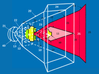
Disclosed is a self-bias circuit for an electrostatic transducer, which is adapted to receive a modulated or unmodulated AC carrier signal from the output of the power amplifier as the input to the bias-circuit. Then, the circuit rectifies the modulated or unmodulated AC carrier signal into a steady DC bias voltage for suitable application across an ESL transducer without affecting carrier signal as it is delivered to the emitter to emit ultrasonic-to-audio, parametric output.
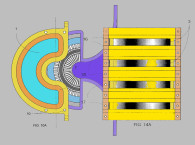
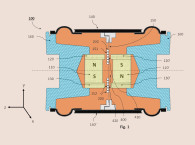
According to the patent, the invention includes a number of variations and configuration details, such as the inclusion of an output inductor, transformer, or auto-former, with an electromagnetic shielded pot core, where a primary can be matched to an amplifier’s impedance, while a secondary is matched to the transducer’s impedance to provide a chosen resonant point.
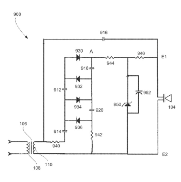
The self-bias circuit may further include a full-wave bridge rectifier that can convert the modulated or unmodulated AC carrier signal into a corresponding DC voltage. Subsequently, a filter capacitor reduces variations of the DC voltage at the output of full-wave bridge rectifier in order to provide a steady DC bias voltage across the transducer.
Amplitude of DC bias voltage can approximately correspond to the highest peak of the AC carrier signal, where maximum achievable DC bias voltage can be determined by the highest peak of a modulated carrier signal.
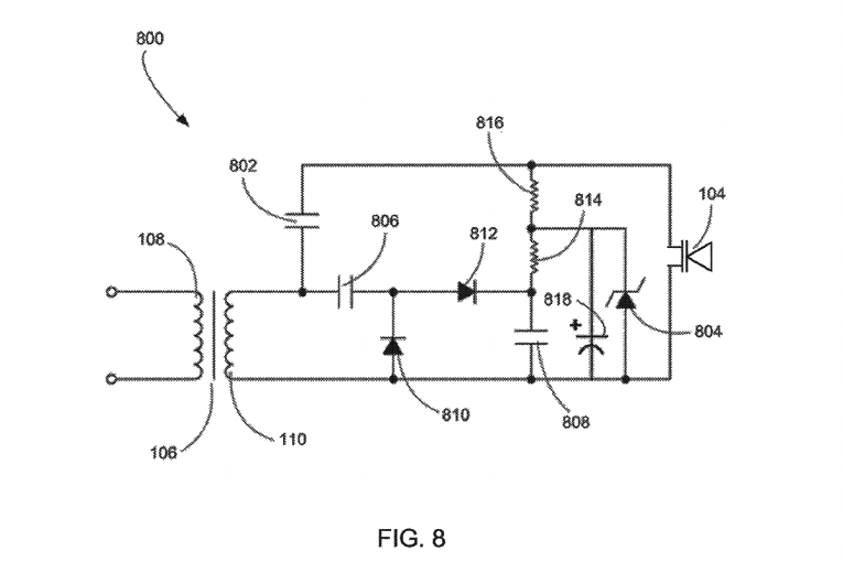
In an additional embodiment, a self-bias circuit does not require the full-wave bridge rectifier for converting the AC carrier signal into DC bias voltage. In this particular embodiment, the self-bias emitter circuit can include a simple voltage doubler, which can be used in conjunction with a filter capacitor to provide a steady and increased DC bias voltage to the transducer, while also coupling a modulated AC carrier signal to the transducer without significant signal attenuation. This self-bias emitter circuit can also include a Zener diode to regulate the amplitude of the DC bias voltage applied across the transducer.
Essentially, the embodiments of a self-bias circuit can use the amplitude of the output signal from the power amplifier to provide suitable DC bias voltage to the electrostatic transducer, eliminating the necessity of auxiliary power supplies and additional power-line wires.
Even though the patent discloses a few circuit configurations that differ somewhat from the prior art, it breaks little new ground, while still illustrating a useful approach to powering electrostatic transducers, particularly those incorporated into a parametric loudspeaker system. If one works in the development of electrostatic loudspeakers or headphones it can be instructive to read this patent, and even more so, to review many of the pertinent references disclosed in the patent that have explored the concept over the last few decades.
As one last observation, it is interesting to notice that the inventor disclosed well over 100 references in the patent. A number of them disclose prior art, or references that have prior art information, that may have informed the examiner such that the patent would not have been allowed.
If one looks at the case file for this patent, it can be seen that the examiner didn’t even refer to any of the prior art that was pertinent to the case, but instead tried to challenge the case with prior art that was not relevant and was easy for the inventor’s attorney to argue against. It is unlikely that the patent examiner was able to wade through all the reference material, and therefore, missed the significant prior art that would have challenged the case.
One approach that can be used to get an application with questionable novelty allowed, even though there is prior art that may bar it from being a legitimate invention, is to “hide” the most damaging prior art among so many references that the examiner may not be able to find it.
Technically, as an inventor, you have met your burden of disclosing all pertinent prior art, but because you have disclosed so much material, very few examiners will review enough of it to find the relevant prior art, and therefore, the odds of having the patent application granted, are significantly increased. VC
This article was originally published in Voice Coil, July 2018.