Coaxial Centerbody Point-Source (CCPS) Horn Speaker System
Patent/Publication Number: US20180359559A1
Inventors: Anthony Allen Bisset (Oakland, CA); Quang-Viet
Nguyen (Aldie, VA)
Assignee: None
Filed: November 11, 2016
Current CPC Class: H04R 1/32 20130101
Published: December 13, 2018
Granted: August 06, 2019
Publication of US10375470B2
Number of Claims: 36
Number of Drawings: 12
Abstract from Patent
The invention relates a horn-based multi-driver wide-bandwidth loudspeaker with a flat-frequency response having the property of controlled acoustic directivity at wavelengths larger than the nominal wavelength supported by the horns’ mouth circumference, which is provided by means of a center-body fitted with acoustic drivers that are acoustically coupled to the walls of the horn enclosure.
Independent Claims
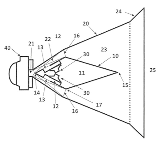
1. An acoustic horn comprising an acoustic enclosure extending along a longitudinal axis, the acoustic enclosure having an acoustically open end, an acoustically closed end, and acoustically closed narrowing sides having interior walls and; an elongated centrally-located having an exterior wall, and a distal vertex and a proximal vertex, the center-body containing one or more acoustic transducers and one or more acoustic ports, the center-body extending along the longitudinal axis and the narrowing sides of the enclosure to form an annular acoustic channel defined by the interior walls of the acoustic enclosure and by the exterior walls of the center-body, at least one high frequency range driver being acoustically coupled to the proximal vertex of the center-body; and the center-body having a rear surface, the rear surface coupled to the narrowing sides, and the center-body further having a frontal surface, wherein the center-body extends along the longitudinal axis in a first plane and in a second plane, and the second plane is inclined relative to the first plane, and in the first plane and in the second plane, the rear surface tapers outward along the longitudinal axis following a surface of the enclosure to a transition, and the first front surface tapers inward along the longitudinal axis from the transition toward the open end, so as to form an expanding annular passage defined by the acoustic enclosure and the center-body exterior wall.
32. An acoustic horn comprising an acoustic enclosure extending along a longitudinal axis, the acoustic enclosure having an acoustically open end, an acoustically closed end, and acoustically closed narrowing sides having an interior wall and; an elongated centrally-located central member having an exterior wall including alternating segments, and a distal vertex and a proximal vertex, the central member containing one or more acoustic transducers and one or more acoustic ports, the central member extending along the longitudinal axis at a variable location and within the narrowing sides of the acoustic enclosure to form an annular acoustic channel defined by the interior wall of the acoustic enclosure and by the exterior wall of the central member, at least one high frequency range driver being acoustically coupled to the proximal vertex of the central member; and the central member having a rear surface, the rear surface coupled to the narrowing sides, and the central member further having a frontal surface, wherein the central member extends along the longitudinal axis in a first plane and in a second plane, and the second plane is inclined relative to the first plane, and in the first plane and in the second plane, the rear surface tapers outward along the longitudinal axis following a surface of the interior wall of the acoustic enclosure to a transition, and the first front surface tapers inward along the longitudinal axis from the transition toward the open end so as to form an expanding annular passage defined by the interior wall of the acoustic enclosure and the central member exterior wall.
Reviewer Comments
Even though it is still somewhat of a rare find in the industry, two attributes of loudspeaker system development, for which there is considerable positive consensus, are that of:
1) Substantially constant directivity vs. frequency; and
2) Acoustic projection from a single, coherent acoustic source
As disclosed in the patent under review, there is a compact high-fidelity multi driver point-source sound reproduction system, which is characterized by high efficiency, low distortion, wide bandwidth, and controlled directivity from a coherent multi-way source.
Many multi-driver/multi-way loudspeakers work on the principle of acoustic summation from a quasi-point source representation as viewed from the listener’s position. This can be seen in a number of common loudspeaker configurations, such as simple two-way systems, or more complex layouts, such as home theater center channel loudspeakers (Woofer-Tweeter-Woofer); large format studio or consumer audio loudspeakers (Woofer-Mid-driver-Tweeter-Mid-driver-Woofer); and in PA sound reinforcement systems where individual horns are aligned on one axis or co-axially nested, or more recently, horns that utilize multiple drivers integrated within a single horn to accomplish improved wavefront coherence and pattern control.
Much of the prior art related to the present invention involves horn loudspeakers combining multiple drivers into a single source such as Mark Engebretson’s “Radiation Boundary Integrator” (US Patent No. 7,134,523); Thomas Danley and Bradford Skuran’s “Unity Summation Aperture” (US Patent No. 6,411,718); Richard Vandersteen’s “Coincident Source Topology” (US Patent No. 20030053644 A1); Ralph Heinz’s “Multiple-Driver Single Horn Loudspeaker” (US Patent No. 5,526,456 A); and what appears to be the granddaddy of the concept, Lee De Forest’s invention titled, “Improvements in or connected with sound reproducing devices,” disclosed in the British patent (GB 303,837) of 1930, which combines a high-frequency reproducer and a low-frequency reproducer through discrete throats that then merge into a common horn mouth.
Some of the cited speaker systems are optimized for high sound pressure levels (SPL), others are optimized for wide dispersion, and some are optimized for high-fidelity. Yet, each of these loudspeaker topologies operates by summation of frequencies produced by multiple, bandwidth- specific drivers (woofer,midrange, tweeter, etc.) used to accurately reproduce music at SPLs sufficiently loud for solitary listeners positioned at mid- or far-field and/or to satisfy large audiences taking part in, what the inventors call, “socially sanctioned rituals of induced hearing loss.” In the case of multi- driver horn loudspeakers, it has been possible to improve wavefront coherence beyond that of traditional discrete horn speakers, yet there remain a number of problems, which limit their full potential.
As stated by the inventors, a significant limitation of multi-driver horn topologies is a “power response disparity” between the midrange drivers and the high-frequency source, where the high-frequency driver is often a compression driver that is located at the horn vertex. The disparity is caused, in part, by the industry standard method (e.g., in the Danley reference) of injecting the midrange frequencies through the outer horn wall with the midrange’s upper bandwidth primarily defined by the acoustic distance between the injection point and the horn vertex.
Because frequencies near half wavelength this distance suffer self- cancellation due to reflected sound waves, (from the midrange driver to the compression driver’s horn throat and back to the midrange driver’s position), the midrange driver exhibits significant cancellation nulls at the fundamental half-wave thus limiting the upper bandwidth available from the midrange driver element and forcing the high-frequency driver to play to lower frequencies than what is often less than mechanically or acoustically optimal.
Furthermore, the usual practice of injecting the midrange acoustic power into the horn is accomplished using an aperture or port located on the horn’s exterior wall. The midrange drivers are coupled into the horn wall through a band-pass chamber formed by the driver’s diaphragm on one side and the horn wall and aperture on the other side. This band-pass assembly is then used to “inject” acoustic power into various locations of the horn’s axial expansion by variation of the band-pass injection ports.
As observed by the inventors, the largest problem with this band-pass injection method is that the acoustic energy entering the horn’s air mass goes through the sidewall port and into a sudden 2-π steradian expansion. This sudden expansion has a large acoustic impedance discontinuity as the sound waves travel from mid-driver diaphragm, through a constricted band-pass aperture and into the horn, resulting in a midrange driver coupling its acoustic power less efficiently into the horn’s air mass at higher frequencies, since there is not a coherent pressure expansion along the horn’s axis.
The inventors suggest that since both these problems affect the midrange driver’s high-frequency bandwidth (and quality thereof), it has become accepted that band-pass aperture-loaded midrange drivers are not used above 1200 Hz to 1500 Hz, thus forcing the high-frequency compression driver (located at the horn vertex) to operate into significantly lower bandwidth than would normally be advisable for high-power sound reinforcement applications.
Such a multi-driver horn loudspeaker relies heavily on its high-frequency compression driver, which is then forced to operate at great SPL, which increases air turbulence and nonlinear heating of the air medium within the compression driver’s passages, thereby producing increasing levels of acoustic distortion, often characterized by the level of harmonic distortion. This high-power requirement for the compression driver also results in increased mechanical fatigue and statistically increased failure rates as compared to compression drivers tasked with operating across less bandwidth starting at higher frequencies.
Another stated problem of current multi-driver horn topologies is that of wavefront interference and diffraction in arrayed (sectoral, cellular, cluster, line, etc.) speaker systems. Because of the difference between the horn’s angle of acoustic expansion and the angle of its outer walls, a compromise must be made between increased mouth-edge diffraction and spacing the array to form a coherent point source. This is because multi-driver horn topologies place the midrange and bass speakers on the outside of the horn wall, which makes the external enclosure geometry significantly larger than the embedded horn’s acoustic geometry.
For the case where forming a larger point-source speaker system from a plurality of horns whose acoustic expansions are not the same angle as their external form factor, designers must separate the horns by 20 to 30 cm to make room for the bulky externally mounted drivers, and this extra separation between adjacent speakers incurs a reduced acoustic coupling between the horn mouths and the potential of increased distortion via diffraction at the horn mouth(s).
In the case where acoustic system designers couple these horn mouths together directly, the angle of co-incidence between the arrayed horns may cause overlapping coverage, which can produce interference based comb filtering. This is typically accounted for by adding extensions or round-overs to each multi-driver horn mouth, which increases the horn’s physical dimensions or array of horns, thereby reducing their fit for use by sound-for-hire companies that transport speakers to locations and by venues where space is limited.
Yet another stated problem of the prior art is the loss of horn directivity and loading/sensitivity at frequencies below the horn’s rated low corner. In multi-driver horns, the mid-bass (150 Hz to 300 Hz) and bass (10 Hz to 150 Hz), bandwidth is compromised in usefulness because it does not exhibit pattern control like the majority of the horn speaker’s bandwidth. Without pattern control across all frequencies reproduced, arrays will exhibit audible interference patterns. Further, without pattern control a positional amplitude response disparity between horn-uncoupled frequencies (bass and mid-bass) and horn loaded frequencies ( midrange and high frequency) will increase in severity as the listener’s distance from the loudspeaker increases, making a flat frequency response loudspeaker that maintains relative spectral balance from near to far field difficult to achieve.
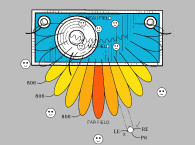
Last, high-frequency lobing is caused by high-frequency energy focusing along a horn’s axis and producing an uneven or “lobed” spatio-frequency response. This results in a sound field where the frequency response changes as the listener comes directly on axis to the speakers’ output. In sound reinforcement where arrays of horn speakers are used, the resulting uneven acoustic is problematic for different listeners within an audience spread across the listening space or when the sound system is moving relative to the audience. Such high-frequency lobing effects undermine the uniform pattern of directivity, which is desirable in commercial or professional sound reinforcement applications where the listener or audience may be widespread, or not stationary.
It is the purpose of the invention to solve these problems by:
- Eliminating the “power response disparity” between the midrange drivers and high-frequency compression driver through efficient wide bandwidth acoustic coupling between the midrange driver and the main horn air mass;
- Reducing the external footprint of the horn improving performance of point and line source arrays by locating the midrange drivers internally to the exterior horn walls;
- Defining the exterior of the horn cabinet the same as the interior acoustic expansion surface, allowing speakers to be accurately placed in an array next to each other without directivity or mouth diffraction issues incurred by exterior cabinet construction which makes precisely arrayed acoustic alignments difficult;
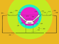
- Maintaining directivity to frequencies below the horns acoustic dimensions, whereby the pattern control applies to all frequencies being reproduced;
- Diminishing the on-axis high and mid-frequency lobing, thereby minimizing the “high frequency lobing” problem;
- and Enabling midrange drivers to be integrated at closer proximity to the central horn vertex where the compression driver is located, thereby achieving improved summation of all audible frequencies and more precise point-source behavior.
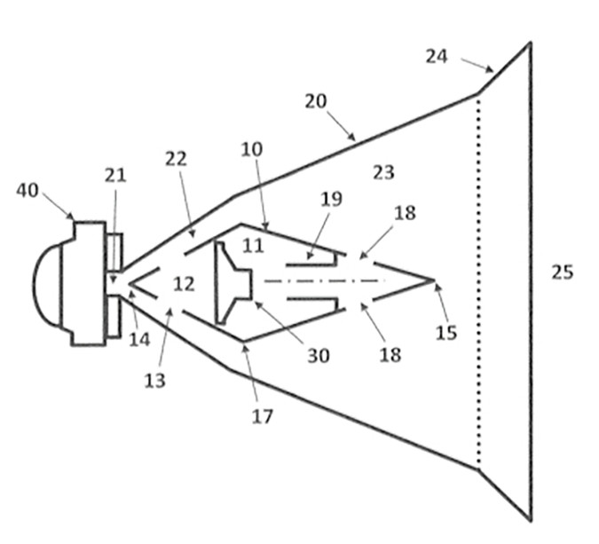
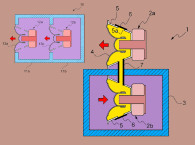
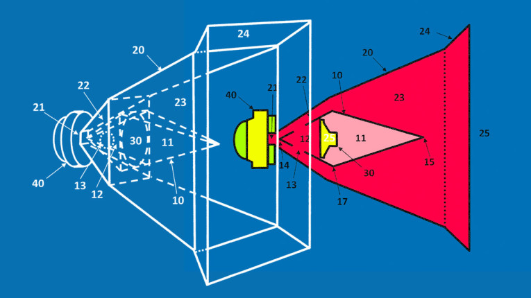
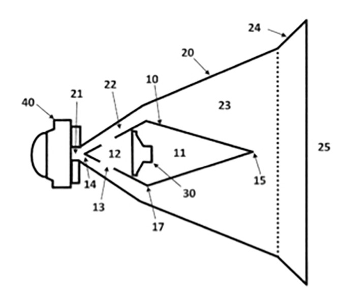
The location of the midrange driver acoustic power injection is located at a point along the annulus, before the termination of the center-body, whereby the annular acoustic channel forms into a unified acoustic pathway. In the preferred embodiment, a high-frequency compression driver is located at the vertex of the horn and the midrange and mid-bass signal sources or resonators are located inside the center-body structure occupying the horn forming an expanding annular acoustic path. A multi-segment annular acoustic lens horn profile is configured to effect variable acoustic output directivity.
The inventor states that there are six primary objectives of the present invention’s center-body midrange and bass-injection method over the current state-of-the-art methods for summation, combinatory or co-axial nested horns. The objectives are:
- To utilize the midrange drivers to inject acoustic power into a thin annulus formed by the interior surface of the exterior horn wall and the exterior surface of the wall of the center-body, thereby enabling the midrange drivers to fully “horn load” and reach frequencies greater than 3 kHz, typically 5 kHz, and as high as 10 kHz, allowing the critical vocal region to be covered by a single driver or set of midrange drivers.
- To allow the high-frequency driver output to be tuned or optimized by the geometry of the center-body to provide the functional equivalent of a phase plug to affect a more uniform, flatter, frequency and polar response without a significant on-axis high frequency lobe.
- To enable the high-frequency driver to only be required to operate at frequencies greater than 3 kHz in order to reduce diaphragm motion and compression chamber turbulence, thus increasing the SPL potential and reducing damaged diaphragms so common in the professional audio/sound reinforcement industry.
- To provide for the midrange and/or bass driver element(s) to be arranged in such a way as to provide a ring-resonator within the center-body with low-frequency output integrating via a duct on the center-body or transported to an inward facing duct located on the exterior horn wall via hollow vanes connected to the center-body. This methodology produces directional horn loaded output at frequencies below the horn’s normally defined acoustic specifications.
- To not have any drivers on the exterior wall, thereby allowing more compact arrays, which have improved phase/power response with reduced comb filtering and diffraction artifacts as compared to previous state of the art solutions.
- To utilize a novel horn profile that is calculated to specify stepped, linear or curved horn wall and center-body wall profiles, which produce a constant directivity for the wavelengths traversing the horn.
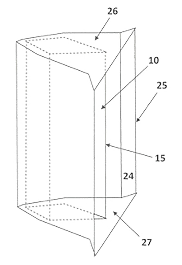
Many of the attributes of this configuration have been tested and proven in previous work by both Curt Graber of Wattre Corp., as disclosed in his 2013 patent, US 8,469,140 “Radial waveguide for double cone transducers” and in 2007 by my Advanced Development Group at American Technology Corp. (now LRAD Corp.) wherein we developed the folded wideband horn system currently used in the “Long Range Acoustic Device” utilized for very high-output, long range, directional, acoustical communications.
Both the Graber and LRAD devices have proven out both, singular and multiple, transducers operating very effectively as a coherent singular acoustic source which can meet the stated objectives when mounted in the configuration disclosed in the current patent under review. This format is both very effective for coherent summation of multiple transducers, over common or differentiated bandwidths, while also lending itself to increased acoustical conversion efficiency of up 5 to 9 dB of increased conversion efficiency over the range of 1 to 3.5 octaves above the horn cutoff frequency, as compared to optimized conventional horn structures. It can also provide a more compact package for a given bandwidth and output capability.
This configuration can deliver both increased acoustic quality (as discussed in the review) and provide increased power density, as exhibited in the “Long Range Acoustic Device” applications. Due to its utility and capability, it is expected this architecture will become more common in the future. Note that the current inventors are also the inventors of the “Compact Wideband Bass and Midrange Horn-Loaded Speaker System” granted as US 9,479,861 already reviewed in Voice Coil. VC
This article was originally published in Voice Coil, March 2019


