Orthogonal Ergonomic Speaker
Patent Number: 9,337,793
Inventors: Jack Nilsson (Canton, OH)
Assignee: Jack Nilsson (Medina, OH)
Filed: January 17, 2013
Class: H03G 3/20 (20130101)
Granted: May 10, 2016
Number of Claims: 18
Number of Drawings: 19
Abstract from Patent
A system and method for an audio system with two or more speakers, drivers, sources, and the like is presented. An audio system includes a first speaker that reproduces sounds in a first frequency range and a second speaker that reproduces sounds in second frequency range. A crossover frequency is formed between the first frequency range and the second frequency range. The first speaker and the second speaker are physically separated by more than one wavelength of the crossover frequency and the first speaker is arranged horizontal with respect to the second speaker.
Independent Claims
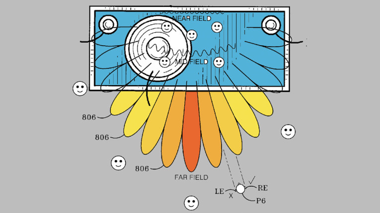
1. An audio system comprising: a first speaker is configured to reproduce sounds in a first frequency range; and a second speaker configured to reproduce sounds in second frequency range, wherein a crossover frequency is at an overlap of the first frequency range and the second frequency range, wherein the first speaker and the second speaker are physically separated by more than one wavelength of the crossover frequency, and wherein the first speaker is arranged horizontal with respect to the second speaker, wherein the first sound source driver and the second sound source driver are configured to generate a radiation lobe pattern so that a person within a far field and facing the first sound source driver and the second sound source driver always has one ear within a lobe of the radiation lobe pattern, wherein the far field begins at a distance from the first sound source driver and the second sound source driver defined by 2D.sup.2/crossover frequency wavelength, where D is a distance between the first sound source driver and the second sound source driver.
11. A sound system comprising a first sound source driver; and a second sound source driver, wherein there is a crossover frequency output by both the first sound source driver and by the second sound source driver due to overlap of the frequency ranges produced by the two drivers, wherein the first sound source driver and the second sound source driver are located greater than one wavelength value apart, wherein the first sound source driver and the second sound source driver are configured to generate a radiation lobe pattern so that a person within the far field and facing the first sound source driver and the second sound source driver always has one ear within a lobe of the radiation lobe pattern, wherein a far field begins at a distance from the first sound source driver and the second sound source driver defined by 2D.sup.2/crossover frequency wavelength, where D is a distance between the first sound source driver and the second sound source driver.
13. A speaker system comprising: a first audio driver configured to generate a first frequency range; a second audio driver configured to generate a second frequency range with a crossover frequency produced by both the first audio driver and the second audio driver, wherein the first audio driver and second audio driver are separated by a separation distance that is more than a plurality of wavelengths of the crossover frequency; wherein when the audio system is in operation a distance between two adjacent cancellation axes between adjacent lobes has a distance 2×, and wherein when the audio system is in operation the value of 2×/10 is equal to or less than the distance between the two ears of an average person, and wherein the first sound source driver and the second sound source driver are configured to generate a radiation lobe pattern so that a person within the far field and facing the first sound source driver and the second sound source driver always has one ear within a lobe of the radiation lobe pattern, wherein a far field begins at a distance from the first sound source driver and the second sound source driver defined by 2D.sup.2/crossover frequency wavelength, where D is a distance between the first sound source driver and the second sound source driver.

Reviewer Comments
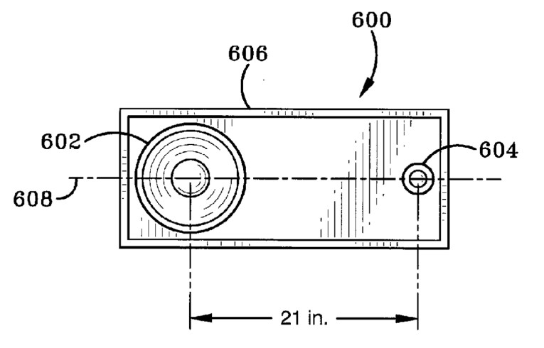
The patent discloses several embodiments that relate to the center-to-center spacing distance of transducers on the front baffle of an audio loudspeaker system. It is standard practice in multiple transducer loudspeaker design to minimize the center-to-center (CTC) spacing of those transducers. At the cross over frequency, the guideline is to have CTC spacing between the high-frequency transducer and the lower frequency transducer to be less than a wavelength and ideally, less than one-half wavelength. At one-half wavelength, there is a cancellation null at the plus and minus 90° angles, relative to the centered, 0° axis (modified somewhat depending on where the actual acoustic centers of the drivers are due to the driver’s phase shift based in its native high and low pass characteristics, and the phase shift added by the crossover. For the purposes of this discussion, we will ignore those additional phase shifts).
As the CTC is increased beyond a half-wavelength, lobes will be formed with one or more nulls between the +90° and –90° angles. For vertical arrangements, this will make for a narrow angle listening window, which due to the additional parasitic phase shifts, may even end up with the listening lobe maxima at an inconvenient angle (e.g., angled downward from the zero axis centered between the drivers). This is one of the reasons that large circular waveguide/horns are avoided, and low-profile waveguides, such as ellipticals, are favored—to keep the CTC to a minimum.
This half-wavelength CTC distance can cause lobing, whether at (or near) the crossover frequency, or for multiple drivers used over a common frequency range (e.g., multiple tweeters covering the same bandwidth).
Horizontally, the problem can be the same, or worse, with the CTC spacing distance of the drivers exceeding half a wavelength. In the horizontal application, the greater than half-wavelength CTC spacing can cause “hot-spots” and “dead-spots” as you move your head horizontally in front of a loudspeaker system.
All of this leads up to the invention disclosed in the patent under review. I have an axiom I have found true in many aspects of audio: a parameter value that is known to be audibly problematic, may become benign, or even advantageous, if increased significantly.
An example: If you have low density, interference-based, comb filtering of an amplitude response through the voice frequency range, the result will be significantly audible coloration. But, if you increase the density of the comb filtering response (adding more peaks and dips, closer together, over the same frequency band) the comb filtering will become so dense that the ear will hear it as a smooth continuous frequency response, as if the peaks and dips did not exist. This patent appears to employ the axiom in the current invention.
The inventor, Jack Nilsson, is an experienced antenna designer with many patents on antenna configurations, antenna directivity, and polar responses.
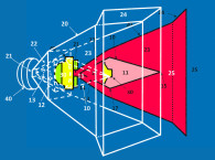
What the inventor observed, is that when one has transducer spacing that is on the order of one wavelength, then there will be lobes with hot-spots and nulls that are wide enough that you can find your head positioned so that both ears can fall within a null-zone of the polar amplitude response. In many cases, in a multi-driver situation it is not practical to move them closer together to eliminate the directivity lobes. So, Nilsson found that if he moved the transducers farther apart, increasing the CTC spacing by more than one wavelength, the increased CTC will cause the lobing density to be so great that they become more closely spaced and all listener positions across the array of lobes are such that both ears never fall into an amplitude null-space.
To optimize the lobe density, you have to create the correct spacing based on the expected listening distance. The width of the nulls and the required number of lobes created across the listening window vary depending on where the listener is positioned in the far field. The invention discusses implementing the increased driver CTC for greater lobe density when used between two drivers at crossover, and also for multiple drivers sharing a common, broad pass band.
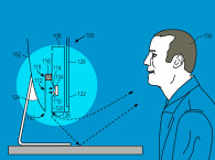
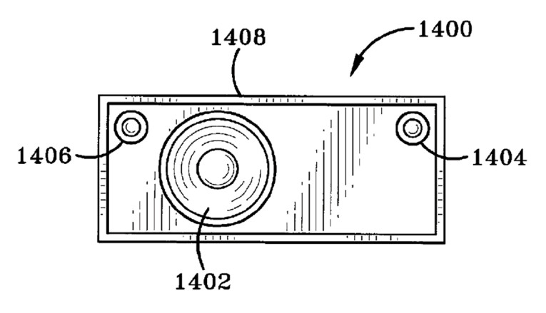
The inventor also discusses how to apply the technique in the horizontal arrangement of transducers, ideally, to establish a lobe density that allows both ears to be illuminated by one or more a lobe-amplitude maxima. To achieve this goal, the inventor discloses a process for determining the lobe density and lob spacing relative to listening distance and the average distance between the listener’s two ears to arrive at the optimal implementation of the approach.
However, there is no discussion of secondary effects, such as that of boundary reflections and any corresponding tonal effects related to lobing nature of the room response. In reviewing the history of loudspeaker configurations, there are many loudspeaker systems, particularly those of the late 1960s and early 1970s, that incorporated tweeters with CTC spacing of more than three-wavelengths, albeit in a rather haphazard manner. This once-popular approach pretty much disappeared by the beginning of the 1980s when observation of directivity control and minimization of lobing became standard practice.
The approach is interesting in its purposeful application of breaking currently established rules and may be useful in certain applications or environments, or when some other compelling transducer or system advantages force a center-to-center spacing that is greater than one-wavelength, and therefore, you might want to further expand the spacing to increase lobe density. VC
This article was originally published in Voice Coil, August 2016.