Loudspeaker
Patent Number: 9,407,979
Inventors: Teppei Yamada; (Tokyo, Japan)
Assignee: ZORZO Co., Ltd. (Tokyo, Japan)
Filed: April 2, 2015
Current CPC Class: H04R 1/02
Granted: August 2, 2016
Number of Claims: 3
Number of Drawings: 2
Abstract from Patent
A loudspeaker includes a hermetically-sealed enclosure, a first driver arranged at outside of the enclosure and along a wall of the enclosure, a second driver arranged at inside of the enclosure and parallel to the first driver across the wall of the enclosure from the first driver, and a pipe communicating the first driver and the second driver. Each of the drivers has a diaphragm, and a frame surrounding the diaphragm. The frame has an opening. The pipe is connected to the opening of the frame of the first driver, penetrates through the wall of the enclosure, and is connected to the opening of the frame of the second driver, and thereby forming one hermetically-sealed space enclosed with the diaphragms and the frames of the two drivers. The second driver is configured to output a signal of opposite phase to that of the first driver.
Independent Claims
1. A loudspeaker, comprising: a hermetically-sealed enclosure; a first driver arranged along a wall of the enclosure outside of the enclosure; a second driver arranged parallel to the first driver across the wall of the enclosure from the first driver inside of the enclosure; and a pipe communicating the first driver and the second driver, wherein each of the drivers has a diaphragm, and a frame surrounding the diaphragm, each of the frames has an opening at a side facing the wall of the enclosure, the pipe is connected to the opening of the frame of the first driver, penetrates through the wall of the enclosure, and is connected to the opening of the frame of the second driver, thereby forming one hermetically-sealed space enclosed with the diaphragms and the frames of the two drivers, and the second driver is configured to output a signal of opposite phase to that of the first driver.
Reviewer Comments
Disclosed is a low-frequency enclosure system incorporating two woofers inter-coupled in a manner similar to what is known as an Isobaric dual woofer enclosure, as first proposed in Harry Olson’s 1954 patent US 2,688,373, “Sound Translating Device,” and later popularized in 1973 by Ivor Tiefenbrun at Linn of Scotland, who coined the name Isobarik and patented his version of the concept in US 4,008,374, “Loudspeaker Systems,” wherein two drivers are coupled in parallel electrically, and in series (one behind the other) acoustically (an example is shown in Figure 2 from the prior art), which allows a halving of the enclosure volume for the same cutoff frequency and half the impedance, (requiring twice the power for the same sound pressure level). Ultimately, one can duplicate the capability of an Isobaric design by building a single driver that duplicates the Thiele-Small parameters of the two Isobaric woofers, summed together. (2 x mass, ½ compliance, 2 x motor strength, ½ the impedance, or essentially, ½ the VAS and twice the motor strength and half the impedance).
The patent claims the Isobaric doesn’t produce the desired result and explains, referring again to Figure 2 from prior art:
“The reason is that air moves slowly, air compresses and expands easily, and thereby the front diaphragm 13a begins to move before air delivered by the driver 12b arrives behind the front driver 12a. Therefore, a fundamental solution of the problem of back-pressure is not achieved.”
To translate, it seems the explanation is based on the incorrect notion of what the Isobaric is supposed to achieve — that the rear woofer is to move inward, and create an “infinite compliance/volume” for the front woofer. (While there are ways to achieve that, using dual amplifiers and asymmetrical drive, but that is a different story for a different time.)
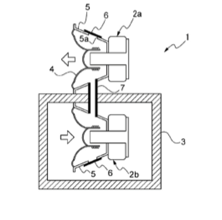
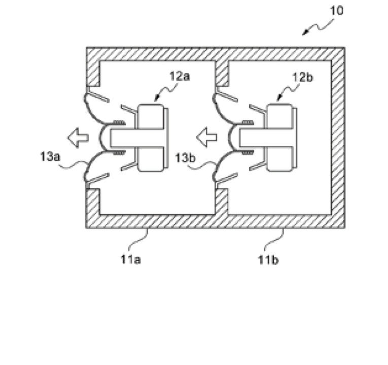
The invention’s new configuration, shown in Figure 1 from the prior art, claims to solve the Isobaric limitation and provide a system of substantial improvement. The present invention aims to remove the problem of back-pressure, or air volume stiffness, of the loudspeaker, and create an infinite compliance for the front driver.
It is essentially disclosed as: The loudspeaker according to the present invention has a hermetically sealed enclosure, a first driver arranged at outside of the enclosure and along a wall of the enclosure, a second driver arranged at inside of the enclosure and parallel to the first driver across the wall of the enclosure from the first driver, and a pipe communicating the first driver and the second driver. Each of the drivers has a diaphragm and a frame surrounding the diaphragm. The frame has an opening. The pipe is connected to the opening of the frame of the first driver, penetrates through the enclosure’s wall, and is connected to the opening of the second driver’s frame, and forming one hermetically sealed space enclosed with the diaphragms and the frames of the two drivers. The second driver is configured to output a signal of opposite phase to that of the first driver. The frame may have a second opening, and a cover member may stem the second opening.
The pipe preferably communicates between the two drivers in the shortest practical distance. Therefore, the space connecting the drivers is very small, and thereby the two drivers operate in exact synchronization with tight motion relation. This improves resonant frequency Fo of the drivers connected by the pipe, and achieves open and clear reproduced sound.
It is claimed that the resonant frequency Fo is reduced by about 20%, according to inventor’s experiment. Considering the purpose of the new system was to provide an improvement to an Isobaric device, it is interesting that a standard Isobaric system will reduce the cutoff frequency by about 27% as compared to a non-Isobaric in the same size enclosure.
Regardless, it is rather fun to work through the puzzle of how it functions and whether it provides an advantage. Unfortunately, it appears to be a rather cumbersome structure to build that ultimately offers no apparent advantage, other than possibly a challenge, and job security, for an industrial designer. VC
This article was originally published in Voice Coil, October 2016.