James Croft originally reviewed the first Resonado patent (US 10743097) in the July 2021 issue of Voice Coil. Now, with these two new patents, you have access to a better understanding of the novel architecture, essentially a full-range driver with one or two oblong or "racetrack" diaphragms and surround form, connected to at least one extended length, blade-like voice coil, immersed in a magnetic field provided by elongated bar magnets. This new review expands on the added innovations and benefits..
Title: Speaker Comprising Split Gap Plate Structure
Patent/Publication Number: US 2022/0386035
Inventor(s): Benny Lee Danovi (Jackson, MI USA)
Assignee: Resonado, Inc.
Filed: 2022-05-27
Granted/Published: 2022-12-01
Number of Claims: 29 | Number of Drawings: 19
Abstract from Patent
An improved speaker design is disclosed. The top and bottom plates in the speaker each contain a recess. These recesses result in gaps in the magnetic field formed in the top and bottom plates. A voice coil is approximately centered in each magnetic gap. As a voice coil moves in and out of the magnetic gap, the total flux passing through the coil remains constant over a wide range of travel, thereby producing a very linear motor force (BL). Optionally, a Faraday ring or a spacer are placed in the recess between adjacent plates.
Independent Claims
1. A speaker comprising: a first assembly comprising a first magnet comprising a first side and a second side, a first top plate adjacent to the first side of the first magnet and comprising a recess, and a first bottom plate adjacent to the second side of the first magnet and comprising a recess; a second assembly comprising a second magnet comprising a first side and a second side, a second top plate adjacent to the first side of the second magnet and comprising a recess, and a second bottom plate adjacent to the second side of the second magnet and comprising a recess; a first magnetic gap formed by the recess of the first top plate and the recess of the second top plate; a second magnetic gap formed by the recess of the first bottom plate and the recess of the second bottom plate; and a voice coil structure comprising a first voice coil centered in the first magnetic gap and a second voice coil centered in the second magnetic gap.
15. A motor comprising: a first assembly comprising a first magnet comprising a first side and a second side, a first top plate adjacent to the first side of the first magnet and comprising a recess, and a first bottom plate adjacent to the second side of the first magnet and comprising a recess; a second assembly comprising a second magnet comprising a first side and a second side, a second top plate adjacent to the first side of the second magnet and comprising a recess, and a second bottom plate adjacent to the second side of the second magnet and comprising a recess; a first magnetic gap formed by the recess of the first top plate and the recess of the second top plate; a second magnetic gap formed by the recess of the first bottom plate and the recess of the second bottom plate; and a voice coil structure comprising a first voice coil centered in the first magnetic gap and a second voice coil centered in the second magnetic gap.
24. A speaker comprising: a first assembly comprising a magnet comprising a first side and a second side, a top plate adjacent to the first side of the magnet and comprising a first recess, and a bottom plate adjacent to the second side of the magnet and comprising a second recess; a second assembly comprising a side structure; a first magnetic gap formed by the first recess; a second magnetic gap formed by the second recess; and a voice coil structure comprising a first voice coil centered in the first magnetic gap between the top plate and the side structure and a second voice coil centered in the second magnetic gap between the bottom plate and the side structure.
• • • • •
Title: Flat Speaker Driven by a Single Permanent Magnet and One or More Voice Coils
Patent/Publication Number: US 11,310,604
Inventor(s): Leeg Hyun Cho (Yongin-si, Korea); Darrell Seyler Adams (Dripping, TX, USA); Youngil Cho; (Chicago, IL USA)
Assignee: Resonado, Inc.
Filed: 2021-01-06
Granted/Published: 2022-04-19
Number of Claims: 22 | Number of Drawings: 21
Abstract from Patent
Embodiments are disclosed of a flat speaker containing a single permanent magnet, a yoke opposite the single permanent magnet, and one or more voice coil plates located between the single permanent magnet and the yoke. The one or more voice coil plates each comprise a bobbin and a coil arranged on one or both sides of the bobbin.
Independent Claims
1. A speaker comprising: a bar magnet comprising a north pole and a south pole; a yoke located a predefined distance from and parallel to the bar magnet, the yoke and the bar magnet separated by a gap; a voice coil plate located between the bar magnet and the yoke, the voice coil plate comprising a coil for receiving an electrical signal; and a diaphragm on a first side of the speaker and attached to a first end of the first voice coil plate; wherein the voice coil plate vibrates the diaphragm in response to force generated by the electrical signal in the coil and a magnetic field between the north pole and the south pole of the bar magnet.
12. A speaker comprising: a bar magnet comprising a north pole and a south pole; a top plate positioned above the bar magnet; a bottom plate positioned below the bar magnet; a first yoke on a first side of the bar magnet, a first air gap created between the first yoke and the bar magnet; a second yoke on a second side of the bar magnet, the second side opposite from the first side and a second air gap created between the second yoke and the bar magnet; a first voice coil plate located in the air gap between the bar magnet and the yoke on a first side of the bar magnet, the first voice coil plate comprising a first coil for receiving an electrical signal; a second voice coil plate located in the air gap between the bar magnet and the yoke on a second side of the bar magnet, the second side opposite the first side, the second voice coil plate comprising a second coil for receiving the electrical signal applied 180 degrees out of phase with respect to the electrical signal as applied to the first coil; a diaphragm on a first side of the speaker and attached to a first end of the first voice coil plate and a first end of the second voice coil plate; wherein the first voice coil plate and the second voice coil plate vibrate the diaphragm in response to a first force generated by the first electrical signal in the first coil and a magnetic field generated by the magnet and directed by the top and bottom plates and a first yoke and a second force generated by the electrical signal applied 180 degrees out of phase with respect to the electrical signal as applied to the first voice coil to the second coil and the magnetic field generated by the magnet and directed by the top and bottom plates and a second yoke.
Reviewer Comments
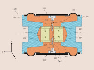
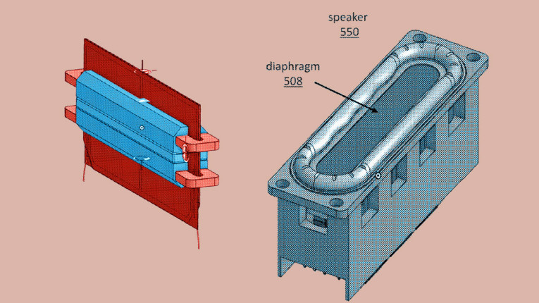
In the July 2021 issue of Voice Coil, we reviewed the first patent (US 10,743,097, “Bidirectional Speaker Using Bar Magnets,” by Leeg Hyun Cho, Youngil Cho, and Christian Femrite) of a new transducer from an advent company, Resonado Labs. The architecture of the device is that of a full-range driver with one or two oblong or “racetrack” diaphragms and surround form, connected to at least one extended length, blade-like voice coil, immersed in a magnetic field provided by elongated bar magnets, as shown in Figure 1.
As stated in the original review, long voice coils combined with the elongated narrow diaphragm have the advantage over conventional drivers of having very little undriven diaphragm surface, as opposed to a circular voice coil mounted in the center of a large (by comparison) circular cone with a lot of undriven diaphragm that can be difficult to control at higher frequencies.
While they can offer certain advantages over the cone and planar loudspeaker types from which they are derived, historically, these systems have not performed particularly well in terms of success and longevity in the marketplace. A few of the drawbacks that have plagued these devices over the years are:
• Stability of the elongated blade voice coils with changes in temperature and humidity, as compared to circular voice coils.
• To achieve adequate stiffness in a flat diaphragm, moving mass vs. cone area is greater than conventional loudspeaker drivers
• The motor is less efficient due to a few factors, including that each voice coil conductor end return being outside of the magnetic gap
• While the form factor can provide very good horizontal dispersion at higher frequencies, the somewhat taller vertical dimension tends to create an awkward vertical polar pattern, wherein for middle and high frequencies above 2kHz to 3kHz the driver will beam dramatically, creating a very narrow vertical listening window for high frequencies.
Additional information about the initial designs is available in an article in the January 2021 issue of Voice Coil written by the CEO of Resonado Labs Brian Cho and titled “A New Standard of Low Depth Racetrack Speaker Drivers with Flat Core Speaker Technology.”
During the last couple years, since the first disclosures of the technology, Resonado Labs has continued to refine and expand the general structural form of the device as expressed in several new patent filings. We will briefly look at two of their more recent patent cases, which are focused on additional formations of the magnetic circuits being incorporated into the transducers.
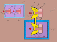
The first new patent application in this review, US2022/0386035, “Speaker Comprising Split Gap Plate Structure” is optimized for greater excursion capability through the use of new dual-gap structures for both the front and rear sections of their blade-form racetrack voice coil as shown in Figure 2 and Figure 3.
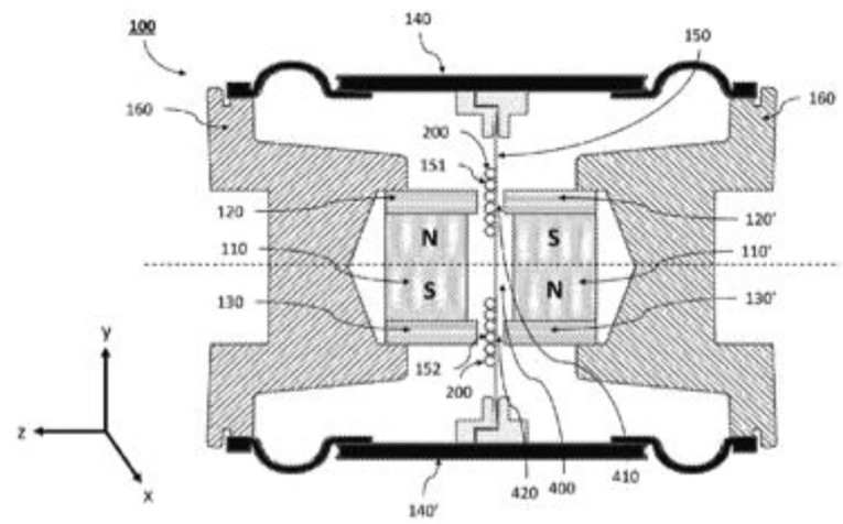
As described in the patent, “Figure 2 depicts a side view of a cross-section of motor 100 for use in a speaker. Motor 100 comprises magnets 101 and 102, top plates 103 and 104, bottom plates 105 and 106, and voice coils 107 and 108. Magnets 101 and 102 are permanent magnets. Top plate 103 is attached to the top part of magnet 101 and top plate 104 is attached to the top part of magnet 102. Bottom plate 105 is attached to the bottom part of magnet 101 and bottom plate 106 is attached to the bottom part of magnet 102. Top plate 103 comprises recess 109, top plate 104 comprises recess 110, bottom plate 105 comprises recess 111, and bottom plate 106 comprises recess 112. Top plate 103, magnet 101, and bottom plate 105 can be referred to as a first assembly, and top plate 104, magnet 102, and bottom plate 106 can be referred to as a second assembly.
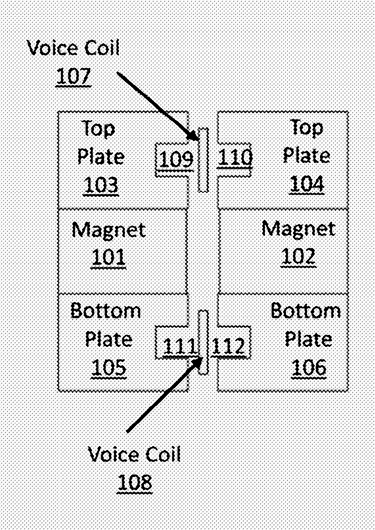
Voice coils 107 and 108 are attached to a structure (not shown), such as a plate, bobbin, printed circuit board (PCB), or other structure. Each voice coil 107 and 108 receives an electrical audio signal from a signal source, and current through each voice coil 107 and 108 generates a magnetic field. Voice coils 107 and 108 can receive the same audio signal, different versions of the same audio signal that are 180 degrees out of phase with one another, or different audio signals.
A magnetic field is induced by magnets 101 and 102, generally in the direction from the north poles (N) to the south poles (S). Here, magnets 101 and 102 are oriented in opposite directions, so that the north pole of one magnet is on the top and the north pole of the other magnet is on the bottom.
Lorentz forces are generated by the voice coils 107 and 108 interacting with the magnetic field generated by magnet 101 and 102, which pushes the voice coil structure containing voice coils 107 and 108 upward or downward, which pushes a diaphragm (as shown in Figure 3) upward or downward, respectively, according to the magnitude of the electrical signal(s) from the signal source(s).
In a preferred embodiment, the winding height of voice coil 107 and 108 is approximately 65% of that of the gap height for by recesses 109 and 110 and 111 and 112 and the recess height and depth are one-third of the total height of the voice coil 107 and 108 and placed at the center of the structure at the gap edge. As voice coils 107 and 108 move in and out of magnetic gaps 109/110 and 111/112, the total flux passing through the voice coil 107 and 108 remains constant over a wide range of travel; therefore, producing a very linear motor force (BL).”
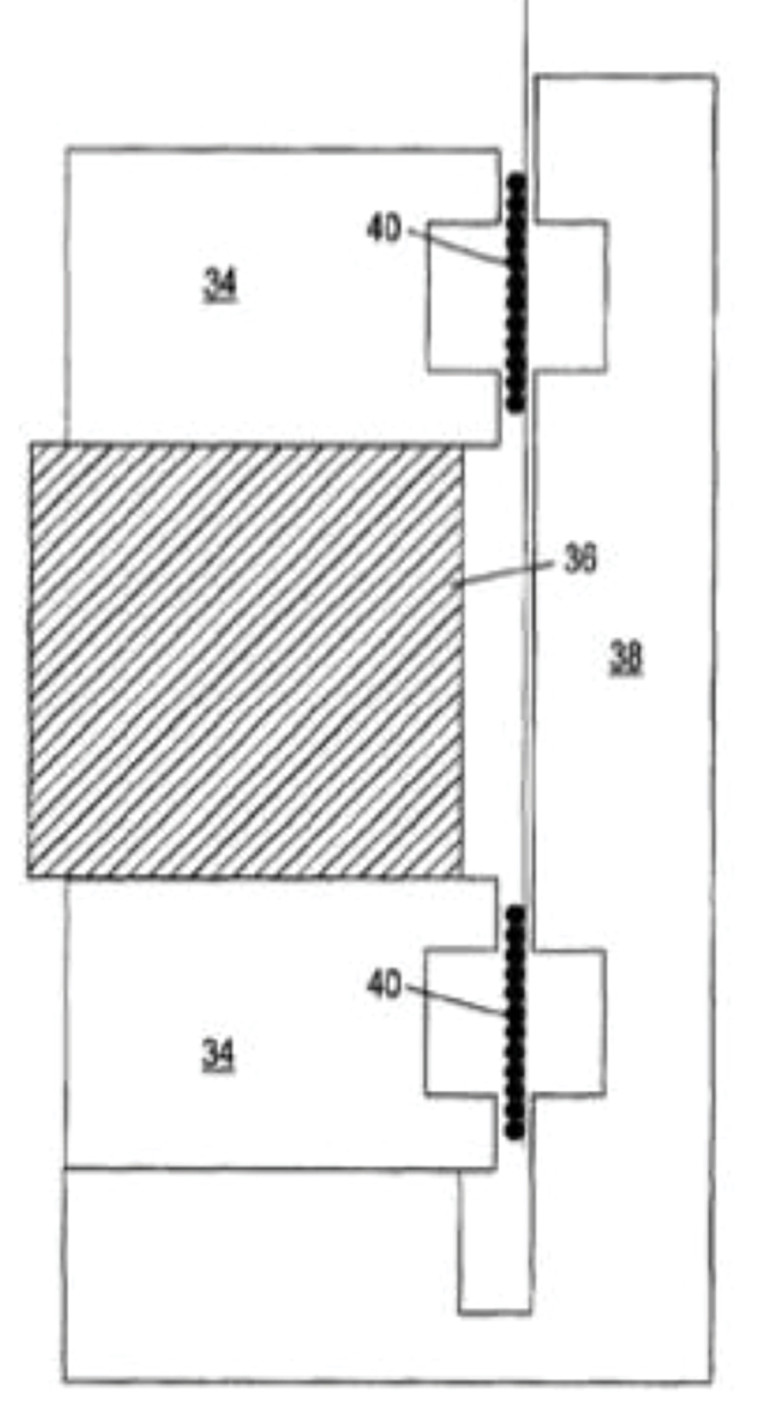
This type of motor structure has the time proven benefit of maintaining low distortion in a high excursion transducer. Time proven, in that those that study such things probably find that this architecture looks very familiar. The rather similar prior art magnetic circuit shown in Figure 4 is from the 2006 patent of David Hyre and Daniel Wiggens (US7,039,213, “Speaker Driver”) which is one embodiment of the well-known XBL2 motor structure. The extensive IP portfolio of Enrique Stiles with his multitude of impressive Mmag patents, including the pertinent US7,006,654, “Push-Pull Electromagnetic Transducer with Increased Xmax,” include prior art relevant to this case as well. These motor formats have proven to excel at producing very high excursion capability while offering reduced distortion and lower moving mass, among other benefits.
There is no reason to believe that this type of motor structure would not also provide excellent, high-excursion, linear performance when utilized in the Resonado transducer architecture.
The second Resonado Labs patent being disclosed here is, US11,310,604, “Flat Speaker Driven By A Single Permanent Magnet And One Or More Voice Coils.”
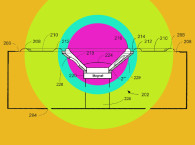
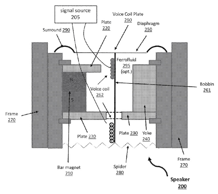
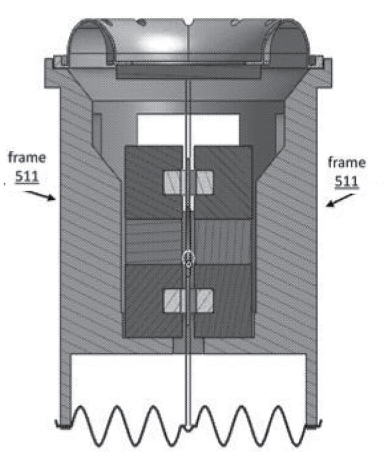
As described in the patent, “Figure 5 depicts a side view of a speaker design utilizing a single diaphragm and a single bar magnet. Speaker 200 comprises bar magnet 210, upper plate 220, lower plate 230, yoke 240, diaphragm 250, and voice coil plate 260. Voice coil plate 260 comprises bobbin 261 and voice coil 262. Speaker 200 further comprises speaker frame 270. On one end, voice coil plate 260 is secured to speaker frame 270 through diaphragm 250 and surround 290, and on the other end, voice coil plate 260 is secured to speaker frame 270 through spider 280 or through a second diaphragm (not shown). Surround 290 comprises a flexible material such as rubber. The dotted lines in plate 230 indicate that plate 230 is a single piece although it appears to be two pieces in this cross-section. For example, plate 230 can be in the shape of an elongated donut.
Optionally, the gap surrounding voice coil plate 260 is filled with ferrofluid 295 comprising iron particles suspended in a liquid carrier. Ferrofluid 295 can help center voice coil plate 260 in the gap and serve as a liquid buffer so that it does not rub up against yoke 240, plates 220 or 230, or bar magnet 210. Ferrofluid 295 also can help fine tune the mechanical damping of the driver depending on the viscosity of the fluid and can increase thermal conductivity of the driver, thereby increasing power rating and decreasing thermal compression that can happen to the sound.
Upper plate 220 is attached to the upper part of bar magnet 210, and lower plate 230 is attached to the lower part of bar magnet 210. Upper plate 220 and lower plate 230 operate as a yoke, which along with yoke 240, contain and direct the magnetic field in the area between the magnet where the voice coil plate 260 resides. Upper plate 220 and lower plate 230 optionally may extend beyond bar magnet 210 into the magnetic gap to increase the magnetic flux density induced in the magnetic gap.
Diaphragm 250 is positioned above upper plate 220, but also could be placed below lower plate 230 instead. Diaphragm 250 must be configured to produce the corresponding frequency range sound accordingly with the size of diaphragm 250. In this embodiment, diaphragm 250 is substantially flat. However, diaphragm 250 instead could be convex or concave, or any shape with respect to the top surface of the frame designed for any application-related acoustic design.”
According to the example discussed, unlike traditional speakers, it is possible to realize rectangular-shaped, flat speakers instead of circular speakers, to simplify parts holding the voice coil plate and multiple diaphragms, to play multi-frequency range sounds at the same time by varying the sizes of diaphragms, and to play a wide range of sounds in general. In addition, the embodiments utilize only a single bar magnet, which substantially reduces the manufacturing costs of the embodiments.
The embodiments allow speakers to be ultra-light and ultra-thin, which perfectly aligns with the demands for speakers used in thin and light objects. By using only one bar magnet instead of more than one bar magnet for this bar magnet-style speaker with a flat voice coil, the embodiments have a significantly reduced manufacturing cost compared to traditional speakers.
The primary novelty in this patent appears to be the simplification of the magnetic circuit to only require a single bar magnet and to use a return steel yoke in place of what is normally the second bar magnet of the Resonado Labs transducer. While it is suggested that this provides a reduction in component and production cost compared to the standard two magnet Resonado Labs format and traditional loudspeaker forms, it is unclear how this cost benefit would actually be realized, due to the fact that for the system efficiency to be maintained, the single bar magnet would most likely need to be approximately twice the size of each magnet in a dual-bar magnet structure, and the return path steel components would be just as plentiful and seemingly require just as much manufacturing time as the dual-bar magnet assembly.
In any case, it would be expected that this construction should work effectively and could possibly have some packaging or form factor benefits in certain applications.
So, it would seem the Resonado folks are continuing to increase the number of forms of their transducer technology with the first of these two patents representing a performance enhancement and the second potentially offering a reduction in the cost of the transducer assembly. It will be interesting to continue to follow their progress and see how their various embodiments are reduced to practice and whether they can provide an advanced performance and value proposition. VC
This article was originally published in Voice Coil, July 2023.