As an experienced patent reviewer and speaker technology expert, Croft adds valuable context to the awarded patent, which apparently fails to mention much of the prior art that supports it. In his text, Croft also helps to better understand the patent's focus and benefits, which are hard to discern from even the published abstract. As he mentions, it is important to understand how a reinvention of an existing technology adds innovation and results of the latest advancements in materials and process science. Or sometimes simply an adaptation of the concept to a different use-model category. Particularly, because this patent mainly opens the doors to a scalable approach that has yet to conquer territory.
Bidirectional Speaker Using Bar Magnets
Patent Number: US 10,743,097
Inventor(s): Leeg Hyun Cho (Gyeonggi-do, Korea), Youngil Cho (Chicago, IL), Christian Femrite (Westminster, CO)
Assignee: Resonado Inc. (South Bend, IN)
Filed: October 21, 2019
Current International Class: H04R 1/24 (20060101)
Granted: August 11, 2020
Number of Claims: 7
Number of Drawings: 13
Abstract from Patent
A speaker comprising a frame; a first magnetic body and a second magnetic body each coupled to the frame and spaced apart by a predetermined distance from each other to form a gap, wherein the first magnetic body and the second magnetic body are arranged such that opposite polarities of the first magnetic body and the second magnetic body are provided at adjacent lateral positions; a first diaphragm; a second diaphragm; and a first voice coil plate having at least one voice coil wound on and coupled to the voice coil plate, the first voice coil plate being located in the gap between the opposite polarities of the first magnetic body and the second magnetic body, wherein the first voice coil plate is coupled to the first diaphragm and second diaphragm.
Independent Claims
1. A speaker comprising: a frame; a first magnetic body and a second magnetic body each coupled to the frame; a first voice coil plate that has at least one voice coil wound and coupled to the first voice coil plate, and is placed in between the first magnetic body and the second magnetic body that have been spaced at a minimum distance so that the first voice coil plate will be able to move due to Fleming’s left hand law; wherein the first magnetic body and the second magnetic body is arranged so that the opposite polarity of each body is facing each other; and a first diaphragm is coupled to a first end of the 1.sup.st coil plate and a second diaphragm is coupled to the second end of the 1st voice coil plate.
Reviewer Comments
In past reviews I have suggested that with certain technologies there seems to be a cycle of rediscovery and “re-invention” about every 10 years. Often it is just a reinvention of the same technology, but other times it can include the added innovation of the latest advancements in materials and process science or an adaptation of the concept to a different use-model category.
One of the types of loudspeaker transducers that tend to get reinvented every decade or so is the full-range driver with an oblong or “racetrack” diaphragm/surround form with long, blade-like voice coils. This format tends to most often be arrived at from two different starting points.

One starting point is that of conventional, circular full-range drivers, wherein one is attempting to realize smoother, more extended high-frequency response and improved dispersion, while still maintaining enough diaphragm area to deliver reasonable output levels at low frequencies. A narrow racetrack form with an extended voice coil driving nearly the full length of a flat, rigid diaphragm can offer advantages in well-behaved bandwidth extension and horizontal dispersion.
Another starting point is that of planar magnetic, film diaphragm transducers that use inefficient fringe magnetic fields to drive conductors that are attached to the diaphragm. In this case, the innovator is attempting to replace the conductors on the diaphragm with blade-like voice coils to create efficient focused fields and to increase excursion capability, while giving up some of the force-over-area drive of a planar magnetic or electrostatic film type transducer.
Regardless of which direction one is coming from, both tend to arrive at a common architecture, based on a rigid planar diaphragm, a racetrack surround, and long blade-shaped voice coils immersed in a magnetic field provided by long bar magnets and magnetically conductive top and back plates. The long voice coils combined with the elongated narrow diaphragm has the advantage over conventional drivers of having very little undriven diaphragm surface, as opposed to a circular voice coil mounted in the center of a large (by comparison) circular cone with a lot of undriven diaphragm that can be difficult to control at higher frequencies.

While they can offer certain advantages over the two loudspeaker types they are derived from, historically, these systems have not faired well in terms of success and longevity in the marketplace. A few of the drawbacks that have plagued these devices over the years are:
- Stability of the elongated blade voice coils with changes in temperature and humidity, as compared to circular voice coils.
- To achieve adequate stiffness in a flat diaphragm, moving mass vs. cone area is greater than conventional loudspeaker drivers.
- The motor is less efficient due to a few factors, including that each voice coil conductor end return being outside of the magnetic gap.
- While the form factor can provide very good horizontal dispersion at higher frequencies, the somewhat taller vertical dimension tends to create an awkward vertical polar pattern, wherein for middle and high frequencies above 2kHz to 3 kHz the driver will beam dramatically, creating a very narrow vertical listening window for high frequencies.
As I’ve mentioned in a previous review, a high-performing version of this format was developed by Dr. Carl Pinfold of Merseyside Acoustic Developments in Liver Pool England, and first disclosed in the May 1983 issue of the British journal, Hi-Fi News & Record Review under the title, “One-way Drive.” The Pinfold device incorporated an elongated racetrack-shaped diaphragm formed from a block of balsa wood, driven by racetrack shaped voice coil interfacing with the diaphragm such that no undriven portion of the diaphragm is more than 10mm from where the coil former is attached to the diaphragm, which ensures that the diaphragm is fairly evenly driven across its surface.
While the units appeared to be handmade with somewhat poor unit-to-unit quality control, the best samples were impressive, providing a very good showing for full-range transducer performance relative to smooth wide-band, frequency response with virtually no signs of cone break-up, while exhibiting wide horizontal dispersion.
Over the last two decades there has been a flurry of new patent applications for these devices, many with similar attributes. Some educational examples are: US2002/0039430, “Electricity-to-Sound Transducer” by Jiro Nakaso; US2007/0076915, “Plane Speaker Having Coil Plate Guide Device” by Joung-Youl Shin and Han Byung-Wan; US2007/0147651, “Speaker Device and Mobile Phone” by Kunio Mitobe and Akihiko Furuto, assigned to Pioneer Corp.; US2008/0205686, “Speaker Unit and Speaker Apparatus” by Takahisa Tagami and Emioko Ikuda, assigned to Sony Corp.; US2014/0219494, “Flat Type Spieakier Combining N Magnet and N+1 Voice Coil Plate” by Don-Man Kim, assigned to Exelway Inc.; US2018/0295451, “Multi-Layer Voice Coil Plate and Flat Type Speaker Comprising the Same” by Dong Hoon Min, Joe Bac Kim, and Soon Kwan Kwon, assigned to ICUBES Co.; and US8,224,015, Speaker Voice Coil Unit, and Method of Manufacturing the Voice Coil Unit” by Emiko Ikeda and Takahisa Tagami, assigned to Sony Corp.

This month’s patent review discusses the latest example of this type of transducer to appear in a patent and being made available by a new startup Resonado, Inc.
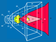
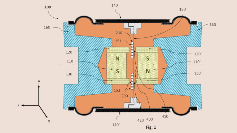
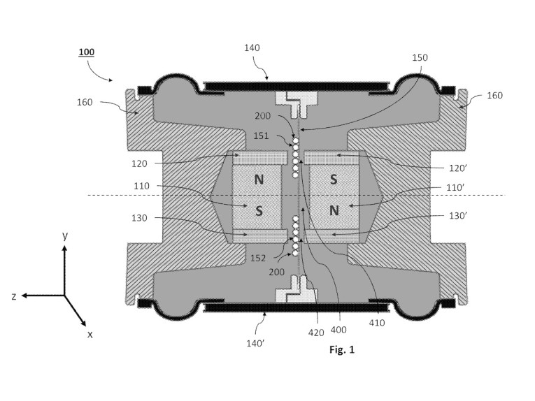
As disclosed by the inventor, the device structure, shown in Figures 1–4, is a bidirectional speaker comprising a frame, a first magnetic structure, and a second magnetic structure, each coupled to the frame and spaced apart by a predetermined distance from each other to form a gap, wherein the first and second magnetic structures are arranged such that opposite polarities of the first and second magnetic structures are provided at adjacent lateral positions. Further included are a first diaphragm, a second diaphragm, and a first voice coil plate having at least one voice coil wound on one or both sides and coupled to the voice coil plate. The first voice coil plate is located in the gap between the opposite polarities of the first and second magnetic structures, wherein the first voice coil plate is coupled to both the first and second diaphragms.
The second diaphragm of the speaker is coupled to the opposite end of the first coil plate from the first diaphragm. The second diaphragm may be a different size or shape, relative to the first diaphragm. The speaker may further comprise at least one additional voice coil plate that has at least one voice coil wound on one or both sides, and coupled to the voice coil plate, wherein the additional voice coil plate is coupled to both the first and second diaphragms. The additional voice coil plate is located in the gap between the first magnetic body and the second magnetic body.
In all embodiments, the transducer is realized without a centering spider due to the fact that the front and rear diaphragm surrounds provide adequate centering such that no spider is required. Figure 5 shows the speaker may be installed in an enclosure the inventor says is configured to guide sound produced by the first diaphragm and sound produced by the second diaphragm in substantially the same direction. The inventor states that, “it is possible to approximately double the speaker’s output in one direction” with this enclosure configuration. It seems to be lost on the inventor that the two signals exiting the front of the enclosure will be out of phase with each other and will therefore provide very little output.

Generally, the invention appears to be a reasonably well-conceived variation on the full-range, racetrack-form transducer. That said, it would not be unreasonable to question the efficacy of the second, or rear, diaphragm when applied in most loudspeaker systems. If one were building a dipole loudspeaker, then this configuration may be useful, but for the more common, monopole applications it seems that the rear diaphragm and the air-space between the diaphragms would merely waste enclosure volume, particularly in small devices where that volume is rather precious. Additionally, these devices already tend to have a mass penalty compared to conventional cone diaphragms, so to double the diaphragm mass for no apparent reason seems to make an inherent shortcoming even worse. Some form of a lightweight spider in place of the secondary diaphragm would seem to be a better solution to align and stabilize the moving system.
Ultimately, it is unclear as to what advantage the new device offers compared to those of the prior art. There doesn’t appear to be any particular novelty expressed in the claims of the invention and the examiner didn’t cite the prior art I listed earlier in this review. But, it is possible that with new materials and construction optimization improvements may be realized.
For those interested in more information and discussion on the device, in the January 2021 issue of Voice Coil, the CEO of Resonado Labs, Brian Cho, wrote an article on the technology titled, “A New Standard of Low Depth Racetrack Speaker Drivers with Flat Core Speaker Technology.” One of the interesting disclosures in the article was a pair of frequency response graphs with the first illustrating the response of the initial use of carbon fiber as the diaphragm material, wherein the amplitude response was substantially absent above 10kHz, but in a second response graph it is shown that by switching to a paper-based honeycomb diaphragm, the response was extended by about one-half octave.
The article also discussed that the technology is substantially scalable, with larger, wider diaphragms being accommodated with the incorporation of more rows of magnets and voice coil blades to keep the force-over-area maximized and maintaining a very small amount of undriven diaphragm and allowing the device to be optimized as a shallow subwoofer driver. It will be interesting to follow the further advancement of the device to see what type of advancements will be made and find out if the technology can be improved beyond what its capability has been in the past. It will also be interesting to see if the Resonado transducer will gain a better stronghold in the marketplace than prior art attempts have achieved with this type of device. VC
This article was originally published in Voice Coil, July 2021