Air Motion Transformer Passive Radiator for Loudspeakers
Patent Publication Number: US US20180152782A1
Inventor(s): Eugene Julius Christensen (Aspen, CO)
Assignee: None
Filed: November 30, 2016
Current CPC Class: H04R 1/2834
Published: May 7, 2019
Number of Claims: 11
Number of Drawings: 32
Abstract from Patent
The present invention provides an improved passive radiator device by utilizing a stacked construction in which there exist two or more generally parallel and separate movable diaphragm sections, in which the relative motion of adjacent diaphragm sections will either move toward each other, or away from each other, as air pressure or sound waves emanating from the interior of a loudspeaker cabinet impinges upon the interior air openings of the present invention.
Independent Claims
1. In a loudspeaker passive radiator, diaphragm means comprising a plurality of closely spaced, substantially parallel movable diaphragms or diaphragm portions defining proximate themselves semi-confined airspaces, and means connected to each of said movable diaphragm portions sealing each of said airspaces with the exception of one side or one edge which remains substantially open, said open sides or open edges of adjacent semi-confined airspaces facing in opposite directions, whereby adjacent movable diaphragms or diaphragm portions defining said semi-confined airspaces will move in opposite directions upon operation, and in which air volumes located in said semi-confined airspaces comprise part of the passive radiator’s total moving mass.
Reviewer Comments
Previously I reviewed the Tymphany stacked, multi-parallel-diaphragm woofer system that was based on low-frequency versions of the original Air Motion Transformer (AMT) work of Oskar Heil in the 1970s.
Eugene Christensen, the inventor of the device in this review, has also been inspired by Heil’s work, in that he has two earlier patents on a rather elegant, omni-directional version of the AMT tweeter-midrange, which he originally disclosed in US Patent 9,124,964, “Wide-range, wide-angle loudspeaker driver” and later in a continuation of the same application, US Patent 9,900696, of the same name. Both are worthwhile reads about an interesting device. In the current patent application, Christensen has revisited his interest in the AMT concept, this time configured as a novel, passive radiator architecture.
The standard passive diaphragm radiator has been commonly known, and applied, for more than 60 years, with the first technical disclosure provided by Harry F. Olson, John Preston, and Everett May, in the Journal of the Audio Engineering Society, (Volume 2, No. 4, p. 219) “Recent Developments in Direct-Radiator High-Fidelity Loudspeakers.”
The original notion that drove the passive radiator development of Olson, et al in 1954, was that the conventional Helmholtz-bass-reflex loudspeaker, (invented by A. L. Thuras in 1930, in US Patent 1,869,178, “Sound Translating Device”), with an open port providing the acoustic mass, was determined to have port particle velocity that was not uniform and that it was also fraught with viscous losses, particularly in the elongated versions.
Therefore, it was thought that a suspended diaphragm, passive radiator of equivalent acoustic mass, would be a superior device, and frequency response measurements were shown to support the idea that the passive diaphragm radiator (or “drone-cone” as it was named at the time) was superior, exhibiting more extended low-frequency capability.
It wasn’t until 20 years later, when Richard Small, in his famous AES papers on the Vented Loudspeakers, (more specifically his “Passive-Radiator Loudspeaker Systems: Analysis and Synthesis,” Journal of the Audio Engineering Society, Volume 22, Issues 8 and 9) explored the passive radiator more thoroughly than Olson. Small’s work showed that it was not superior to an optimally designed ported equivalent, and in fact was slightly inferior, due to the addition of the compliance parameter in the passive radiator suspension. To the extent that the passive radiator had less than infinite compliance, it developed a notch in the high-pass characteristic, causing a reduction in output near the cut-off frequency.
That said, the passive radiator has continued to be useful, particularly where the enclosure volume is too small to incorporate a reasonably sized port that can also provide low loss and turbulence. So, in small bass reflex enclosures, passive diaphragm radiators have found a practical application.
One accepted aspect of passive radiator implementation is to specify the PR diaphragm surface area to be at least twice that of the active transducer diaphragm, as the total cubic volume displacement of the passive radiator at the tuning frequency (FB) will be at least twice that of the active radiator in the pass-band. Since the primary use of passive radiators tends to be with small loudspeaker enclosures, it can be problematic to have the diameter of the passive radiator be significantly larger than of the active transducer, even though the requirements call for a larger device.
The invention under review addresses the packaging issue with a new format for the passive diaphragm radiator. Christensen acknowledges that a main drawback of conventional passive radiators is that the single moving diaphragm of a conventional passive radiator must be made very large, or must have a large amount of linear travel available, or both, in order to provide low-distortion, low-frequency output capability. This suggests that a conventional passive radiator will require a large amount of surface area when mounted on the loudspeaker cabinet, requiring either at least one large surface area on the enclosure, and/or, restricting the available locations where it may be mounted.
Other drawbacks suggested by the inventor are that large amounts of mechanical vibration can be passed onto the loudspeaker cabinet through the passive radiator frame as the suspension and diaphragm are driven back and forth, and also, the large amount of linear travel typically required, can result in unwanted, distorted modes of movement such as rocking and non-linear motion at the extremes of excursion.
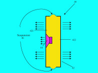
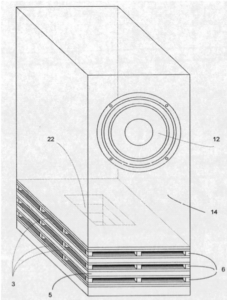
This invention utilizes a stacked, “air motion transformer”-like architecture, incorporating two or more generally parallel and separate moving diaphragm sections, in which the relative motion of adjacent diaphragm sections will either move toward or away from each other, as air pressure or sound waves emanating from the interior of a loudspeaker cabinet impinges upon the interior air openings of the new coaxially layered, passive radiator structure (see Figure 4 and Figure 5).
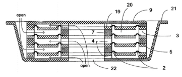
The inventor was originally inspired by Heil’s U.S. Patent 3,636,278, wherein, Heil described a type of high-frequency, actively powered loudspeaker driver which came to be known as an “air motion transformer,” in which sound is produced through the operation of a layered or folded diaphragm operated in such a way that adjacent moving portions of the diaphragm assemblies will always move either away or toward each other, depending on the direction of electric current flow in conductors attached to the moving diaphragm sections.
It is claimed by the inventor that by adapting this actively driven “air motion transformer” principle to be utilized as passive, pneumatically driven, low-frequency “air motion transformer” devices, which by way of utilizing the air masses that have been trapped between adjacent diaphragm sections as part of the total moving “acoustic-mass,” can result in the inventive passive radiator device exhibiting lower distortion, greater sound pressure capability, reduced external vibration, a smaller form factor, and the same or lower total cost than traditional, conventional passive radiator devices.
In a variation of the present invention, multiple interactive magnetic sections may be attached to the passive radiator’s various moving components to provide part, or all, of the suspension of the moving components, and which may also act to limit over-excursion of the moving components at high output levels — keeping them from slamming into each other. The invention is novel and clever and certainly may provide packaging flexibility that would not be possible with conventional passive radiator structures.
In terms of the performance advantages, it remains to be proven as to whether the invention would actually result in lower distortion, greater sound pressure capability, a smaller overall form factor, and whether it can be built for lower or even the same total cost as standard passive radiator devices.
It may reduce enclosure surface vibration due to its natural push-pull arrangement, but that remains to be proven in practice. The idea that the “air pockets” between the diaphragms would increase the acoustic mass, acting somewhat like the acoustic mass confined within a port, but just as a port volume must be subtracted from the effective enclosure volume. These “acoustic mass’ volumes” also be subtracted from the total enclosure “compliance volume” reducing the efficiency of the Helmholtz resonance. Additionally, considering that the surround resistive and stiffness attributes result in system losses, having a multiplicity of small suspensions would make it more difficult to maximize the compliance and minimize resistive losses, compared to a single large surround suspension and the additional magnetic suspensions of the invention could make it even worse in this regard.
Ultimately, the major benefit would appear to be that of a packaging advantage, which if the losses can be managed, might have significant value. Kudos to the inventor for outside-of-the-box thinking. VC
This article was originally published in Voice Coil, August 2018 issue