Acoustic Passive Radiator Rocking Mode Reducing
Patent/Publication Number: US 7,568,552
Inventors: Roman Litovsky (Newton, MA); Jingyi Liu (Marlborough, MA); Roger Mark (Barrington, RI); and Nachiketa Tiwari (Mansfield, MA)
Assignee: Bose Corp. (Framingham, MA)
Filed: January 15, 2004
Current CPC Class: H04R 7/20 (20130101)
Granted/Published: August 4, 2009
Number of Claims: 15
Number of Drawings: 16
Abstract from Patent
An acoustic passive radiator that controls “rocking mode” vibration. An acoustic passive radiator includes a diaphragm for radiating acoustic energy. The diaphragm has a perimeter portion and a central portion. The perimeter portion is thicker than the central portion. The passive radiator further includes a passive radiator suspension. The suspension includes a skin element encasing the diaphragm. The skin element comprises a surround for physically coupling the passive radiator to an acoustic enclosure, pneumatically sealing the diaphragm and the enclosure. The surround has a non-uniform width. The passive radiator a non-pneumatically sealing, non-surround, non-spider suspension element. The non-surround suspension element and the surround co-act to control the motion of the diaphragm and to support the weight of the diaphragm.
Independent Claims
1. An acoustic passive radiator, comprising: a diaphragm for radiating acoustic energy, said diaphragm having a perimeter portion and a central portion, wherein said perimeter portion is thicker than said central portion; a passive radiator suspension, said suspension including a skin element, said skin element encasing said diaphragm, said skin element comprising a surround for physically coupling said passive radiator to an acoustic enclosure and pneumatically sealing said diaphragm and said enclosure, said surround having a width, wherein said width is non-uniform; and a non-pneumatically sealing, non-surround, non-spider suspension element, wherein said non-surround suspension element and said surround co-act to control the motion of said diaphragm and to support the weight of said diaphragm.
2. An acoustic passive radiator, comprising: a diaphragm for radiating acoustic energy; a surround for pneumatically sealing said diaphragm and an acoustic enclosure; and a plurality of discrete, non-surround, non-spider suspension elements for physically coupling said diaphragm and said acoustic enclosure, wherein said non-surround suspension elements and said surround co-act to control the motion of said diaphragm and to support the weight of said diaphragm.
8. An acoustic passive radiator, comprising: a diaphragm for radiating acoustic energy by pistonic vibration through an operating frequency range; a single surround for pneumatically sealing said diaphragm and an acoustic enclosure, wherein said surround is constructed of a solid polyurethane; and a plurality of discrete, non-surround suspension elements, wherein said non-surround suspension elements and said surround work together to control the motion of said diaphragm and to support the weight of said diaphragm.
13. An acoustic passive radiator, comprising a diaphragm for radiating acoustic energy; a surround for pneumatically sealing said diaphragm and an acoustic enclosure, wherein said surround comprises a single element and has a non-uniform width; and a plurality of discrete, non-surround suspension elements, wherein said discrete suspension elements and said surround co-act to control the motion of said diaphragm and to support the weight of said diaphragm.
Reviewer Comments
Particularly with the increasing popularity of miniaturized systems, the application of the passive diaphragm radiator, as the acoustic mass component in a bass reflex enclosure, is becoming standard practice in the low-frequency portion of the system. These systems have a few parameter demands that can exceed the capability of many conventional approaches to passive radiator design, some of which are:
For a given tuning frequency, the smaller the system, the greater the acoustic mass requirement of the passive radiator.
In many of the miniaturized devices, a passive diaphragm radiator with a thin form factor is essential to maintain compatibility with packaging requirements.
A third factor with passive diaphragm radiators, at all scales, is that they often need to be formed into rectangular shapes to maximize surface area while matching the face print to the most common enclosure forms.
In the first case, the increased mass requirement can put great stress on the surround suspension, in terms of gravitational sag or tilt of the diaphragm. The second factor of thin form factor exacerbates the first issue by not providing a deep passive radiator with two spaced apart suspensions to establish stability to avoid static sag and dynamic rocking of the diaphragm during extended excursions.
The third issue of applying non-circular, or rectangular diaphragm forms, can be problematic due to the conventional suspensions exhibiting binding or non-linear compliance at the point of abrupt changes in radius.
Disclosed in the patent under review is an interesting configuration that addresses the passive radiator suspension functions of sealing the periphery of the diaphragm attachment to the enclosure, and suspending the diaphragm to stabilize the physical mass from sagging or rocking the suspension and providing linear compliance during the specified range of excursion displacement, while adapting to any diaphragm shape by separating the functions between two different, parallel suspension types.
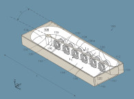
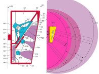
Looking at the example drawings in Figure 1 and Figure 2, it can be seen that the diaphragm 10 has a first roll suspension 12 for sealing and connecting the diaphragm to the enclosure. The unique, inventive component is that of a second, and parallel, suspension system that is shown as a multiplicity of suspending “straps” 32 placed around the periphery of the diaphragm.
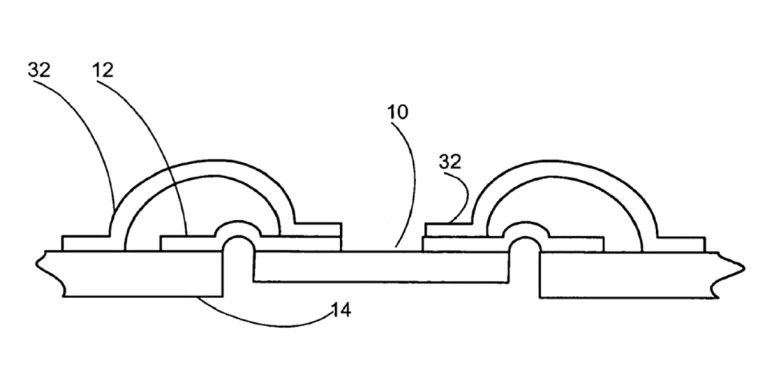
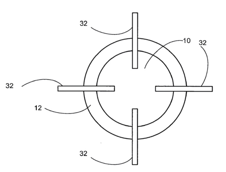
By separating the suspension functions of mounting/sealing the passive diaphragm to the enclosure and stabilizing the diaphragm during static and dynamic conditions, one can better optimize both functions when using high mass diaphragms, thin form factor passive radiators, and non-circular diaphragm shapes, one has the opportunity to better address the three issues discussed above.
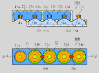
Figure 3 shows a top, plan view of a rectangular, or what is known as a racetrack form of a diaphragm, for which conventional, prior art systems often exhibit compromised performance due to variable width suspensions and/or suspensions must traverse tighter radii at each of the four corners, which can exhibit reduced or non-linear compliance during dynamic excursions. By introducing the secondary suspension elements 32 at the four positions shown the requirements of the primary suspension 12 can be relaxed and optimized to work with suspension 32 to achieve a more linear and distortion free suspension system.
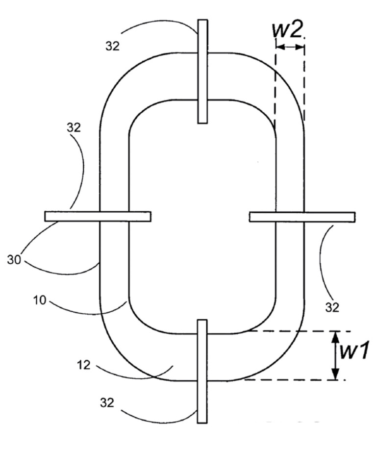
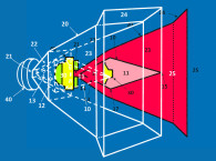
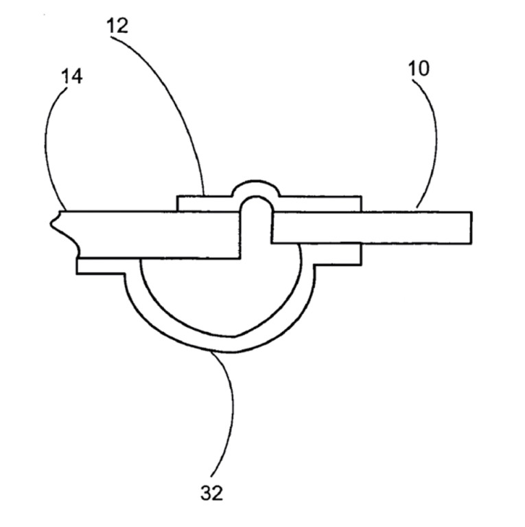
Suspension 12 parameters are also relaxed from having to support unusually high mass diaphragms and stabilizing the diaphragm during large excursions, as secondary suspension 32 can either support or dominate this function. As Figure 4 illustrates, the primary suspension 12 and secondary suspension 32 can also be placed on opposite sides of the diaphragm, which may be advantageous relative to efficient packaging and/or further enhancement of suspension stability.
In most embodiments the primary suspension 12 is recommended to be made with standard materials such as polyurethane while the secondary suspension 32 is formed from spring steel and in one example provides dimensions of 0.15 mm steel thickness, 3.05 cm wide, and 3.05 cm long.
While this reviewer is unaware of any prior art precedent for this type of suspension system being applied to a passive radiator, similar suspension configurations were applied to “active” transducers in the mid-1980s when they were fabricated by the late David Graebener while he and I were developing high output transducers for use in the extreme temperature, caustic environments of active noise cancellation exhaust systems.
In these cases, stainless spring steel loops were found to be quite effective in providing a linear, high-stability suspension function during large excursions, even when employing high mass, non-circular diaphragms. In the case of active transducers, the avoidance of any spurious rocking motions are even more critical than in passive radiators, due to the tight gaps surrounding the voice coil.
Therefore, with past attempts in applying this approach to active drivers showing promise, it is expected that this type of suspension, if properly optimized, would perform quite well when applied to the reduced requirements of passive radiators. VC
This article was originally published in Voice Coil, December 2018