Transmission Line Loudspeaker
Patent Application Number: 20150071473
www.freepatentsonline.com/y2015/0071473.html
Inventors: Geoffrey C Chick (Norfolk, MA); Carl Jensen
(Waltham, MA); and Brian M. Lucas (Marblehead, MA)
Assignee: Bose Corp. Framingham, MA, US
Filed: May 29, 2014
US Class: 381/345
Published: March 12, 2015
Number of Claims: 21
Number of Drawings: 26
Abstract from Patent
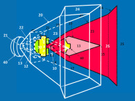
An electro-acoustic driver including an acoustic waveguide includes an enclosure, an acoustic transmission line formed within the enclosure, and a plurality of acoustic transducers contained within the enclosure and disposed along a length of the acoustic transmission line. Each acoustic transducer is configured to emit acoustic energy directly into the acoustic transmission line at two separated locations along the length of the acoustic transmission line.
Independent Claims
1. An acoustic waveguide system, comprising: an enclosure having a closed end and an open end; an acoustic transmission line within the enclosure; and at least one electro-acoustic transducer disposed along a length of the acoustic transmission line to emit acoustic energy directly into the acoustic transmission line, and constructed and arranged to prohibit exciting at least one resonant mode above a fundamental resonant mode of the acoustic waveguide system.
13. An acoustic waveguide system, comprising: an enclosure having a closed end, an open end, and an internal wall; an acoustic transmission line within the enclosure; and at least one electro-acoustic transducer disposed along a length of the acoustic transmission line to emit acoustic energy directly into the acoustic transmission line, wherein the at least one electroacoustic transducer is coupled to the internal wall such that a front side and a rear side of the electro-acoustic transducer are symmetric about a point along the length of the acoustic transmission line where the at least one electro-acoustic transducer prohibits exciting at least one resonant mode above a fundamental resonant mode of the acoustic waveguide system.
20. An acoustic waveguide system, comprising: an enclosure having a closed end and an open end; a tapered acoustic transmission line within the enclosure, the tapered acoustic transmission line comprising internal and external walls, each having a curved geometry; and the at least one electro-acoustic transducer disposed along a length of the acoustic transmission line to emit acoustic energy directly into the acoustic transmission line, wherein the at least one electro-acoustic transducer is positioned along the acoustic transmission line in the enclosure to drive at least one resonant mode above the fundamental resonant mode at a same amplitude and phase on a front side and a back side of the at least one electroacoustic transducer.
Reviewer Comments
Almost 10 years ago, Tom Danley filed a patent and introduced his Tapped Horn loudspeaker architecture to the professional systems marketplace. His device was a modern interpretation of similar recirculating, quarter wave air-columns, first developed in the 1950s by Peter Tappen and William Glenn, and variations “reinvented” approximately every decade thereafter, with the JBL Air Coupler in the 1960s, James Croft in the 1970s, Saeki Shuji in the 1980s, Arnold Klayman and Junichi Hayakawa in the 1990s, Danley in 2006, and now almost a decade later we have Geoffrey Chick, et al developing the Bose variation on the concept in 2014.
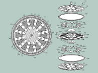
The Bose patent discloses a folded wave column with at least one driver mounted on a central dividing wall so that both polarities of the driver diaphragm are within the air column. The inventors refer to it as an “acoustic transmission line” but suggest that the system has an opposite taper (positive instead of negative) compared to transmission lines and doesn’t use damping material throughout the line — which, structurally, seems to look more like a recirculating, quarter wave air-column or tapped horn than a standard acoustic transmission line.
Quarter wave air columns, due to resonant support, usually placed at each odd quarter wavelength relative to the column length, provide good efficiency and high output with reduced excursion, also tend to have a set of modal side effects that can be difficult to tame. Most often the primary issues are related to excess output at the three-quarter wavelength frequency of the air column, and cancellation nulls at the one-wavelength frequency and multiples thereof.
Prior art work with quarter-wave pipes has shown that positioning the transducer at a one-third multiple point along the length of a wave column can minimize the three-quarter wavelength peaking. One of the positioning guidelines of the Bose patent suggests mounting the transducer at a point one-third of the column length from the device’s mouth.
A primary aspect of the patent is the use of multiple transducers along at least a portion of a length of the structure’s divider panel(s). Frequency responses show that this arrangement appropriately applied, effectively control both the three-quarter wavelength peaking and at least one of the one-wavelength cancellation dips, creating a wider bandwidth device than what is normally realized with a wave-column or tapped horn.
Several of the approaches illustrated in the patent application can provide good improvements in smoothing and extending the system’s response, but usually at a trade-off of compromising the output at the low-end cutoff frequency and other output capabilities for a given transducer Sd.
It is interesting to note that more than four years ago David Graebener had built and tested many of the multi-driver forms that are disclosed in the Bose patents, including a device substantially the same as the one shown in Figure 1. Graebener had realized very good results from several of his prototypes, providing even more significant improvements than what is illustrated in the graphs of the Bose application.
The recirculating quarter-wave air column, and modern version as a tapped horn, as available as a commercial product, has a lot of “untapped” potential that has yet to be realized in commercially available products. This Bose patent (and a companion parent case published at the same time) provides some of what is to come as the next generation improvements in tapped wave columns.
A key element in the Bose claims is the statement, “...constructed and arranged to prohibit exciting at least one resonant mode above a fundamental resonant mode of the acoustic waveguide system.” This would tend to refer to the peaks at the odd, quarter-wave multiples, but not necessarily the dips. They can be the result of an out-of-phase cancellation, not a resonant mode, per se.
In terms of the legal aspects of the claims, while they are an improvement claim over the Danley device, the Bose device appears to still infringe on the Danley tapped horn patent claims, so it will be interesting to see if Bose will have the right to practice its device before the Danley patent runs its 20-year course. Ultimately, the patent teaches interesting and useful techniques applied to quarter-wave air-column, tapped horn type waveguides and is a worthwhile study for those interested in such systems. VC
This article was originally published in Voice Coil, June 2015.