Planar Speaker System
US Patent Number: 8948441
www.freepatentsonline.com/8948441.pdf
Inventor: Zhijun Zhao (West Bloomfield, MI)
Assignee: Harman International Industries, Inc. (Northridge, CA)
Filed: March 14, 2012
US Classes: 381/430
Granted: February 3, 2015
Number of Claims: 11
Number of Drawings: 10
Abstract from Patent
A planar speaker system may include a bottom frame having a cavity. Within this cavity a plurality of magnets may be arranged to form a substantially circular pattern. A diaphragm that includes a plurality of electrically conductive traces may be connected to the bottom frame and extend across the cavity of the bottom frame.
When alternating current flows through the electrically conductive traces, the diaphragm may vibrate in response to the interaction between the current flowing in the electrically conductive traces and the magnetic field, thereby producing sound. The planar speaker system may include a top frame having a cavity, and a second set of magnets may be disposed in the cavity of the top frame.
Independent Claims
1. A planar speaker system comprising: a bottom frame having a cavity, where the bottom frame is substantially circular in shape and has an outer diameter and an inner diameter, and where the cavity of the bottom frame is substantially circular in shape; a plurality of magnets disposed in the cavity of the bottom frame, the plurality of magnets circumferentially spaced to form a substantially circular pattern. The circular pattern cis oaxially aligned with a central axis of the planar speaker system, wherein the plurality of magnets are each substantially trapezoidal in shape; a top frame connected to the bottom frame, where the plurality of magnets are located between the bottom frame and the top frame where the top frame is formed to include a plurality of openings arranged in a substantially circular pattern around a central axis of the top frame; a diaphragm which is substantially circular in shape and has an outer diameter and an inner diameter, the diaphragm having a plurality of circumferentially spaced electrically conductive traces formed thereon, each conductive trace having a central region without conductive traces, the diaphragm extending across the cavity of the bottom frame; an annular ring connected to the outer diameter of the bottom frame and the outer diameter of the diaphragm, where the annular ring is located between the outer diameter of the bottom frame and the outer diameter of the diaphragm to couple the outer diameter of the bottom frame to the outer diameter of the diaphragm; and a pole piece connected to the inner diameter of the bottom frame and the inner diameter of the diaphragm.
7. A planar speaker system comprising: a bottom frame having a cavity, wherein the bottom frame is substantially circular in shape and has an outer diameter and an inner diameter, where the cavity of the bottom frame is substantially circular in shape; a plurality of magnets disposed in the cavity of the bottom frame, the plurality of magnets circumferentially spaced to form a substantially circular pattern; a diaphragm which is substantially circular in shape and has an outer diameter and an inner diameter, the diaphragm having a plurality of circumferentially spaced electrically conductive traces formed in a substantially circular pattern, each conductive trace defining an area without conductive traces, wherein a border of each magnet is generally aligned with one of the plurality of conductive traces, the outer diameter of the diaphragm being connected to the outer diameter of the bottom frame and extending across the cavity of the bottom frame; where the diaphragm has an inner diameter an annular ring connected to the outer diameter of the bottom frame and the outer diameter of the diaphragm, where the annular ring is located adjacent to the outer diameter of the bottom frame and the outer diameter of the diaphragm to connect the outer diameter of the bottom frame to the outer diameter of the diaphragm; and a pole piece adjacent to the inner diameter of the bottom frame and the inner diameter of the diaphragm.
11. A planar speaker system comprising: a substantially circular bottom frame having a cavity, an outer diameter and an inner diameter, where the cavity of the bottom frame is substantially circular in shape; a plurality of magnets disposed in the cavity of the bottom frame, the plurality of magnets circumferentially spaced to form a substantially circular pattern; a substantially circular top frame connected to the bottom frame, where the plurality of magnets are located between the top frame and the bottom frame, where the top frame has a plurality of openings arranged in a circular pattern around a central axis of the top frame; a diaphragm having a plurality of circumferentially spaced electrically conductive traces formed thereon, each conductive trace defining an open space without conductive traces, wherein a border of each magnet is generally aligned with the open space of one of the plurality of conductive traces, the diaphragm being connected to the outer diameter of the bottom frame and extending across the cavity of the bottom frame; where the diaphragm has an inner diameter; a pole piece connected to the inner diameter of the bottom frame and the inner diameter of the diaphragm; and an annular ring connected to the outer diameter of the bottom frame and the outer diameter of the diaphragm, where the annular ring is located between the outer diameter of the bottom frame and the outer diameter of the diaphragm to connect the outer diameter of the bottom frame to the outer diameter of the diaphragm.

Reviewer Comments
Planar magnetic transducers, while having many differentiating attributes relative to conventional dynamic drivers, are often preferred for their thin form factor, allowing them to be utilized in certain environments that have shallow mounting spaces where a standard transducer may not fit, such as in-wall systems and automotive applications.
The majority of prior art planar magnetic transducers are constructed with multiple, elongated and parallel rows of magnets, which causes most of the transducers to be configured with a square or rectangular form factor. The assignee of the current invention, Harman International, has an automotive division that is one of the largest providers of automobile sound systems. They were also licensees of the Graebener planar magnetic patents reviewed in Voice Coil, March 2015.
There has been a desire among the automotive sound system suppliers, including Harman Automotive, to have the transducer configurations conform to a standard set of mounting cutout sizes and shapes, with most being that of an oval or circular form. Even though the standard planar magnetic transducers provided the desirable thin form factor, the mounting outline shapes were not generally adaptive to standard mounting holes, unless a frame was added. Adding the frame would make the diaphragm surface area substantially less than the total structure surface area; therefore, reducing output for a given mounting area.
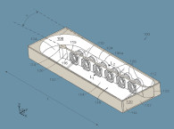
To address the issue and provide a standard circular format while also maximizing diaphragm surface area, the configuration disclosed in the patent was developed. The device can be realized in either a single-sided drive (magnets adjacent just one surface side of the transducer), or a double-sided drive (magnets adjacent both surface sides of the diaphragm). Figure 1 of this patent illustrates a view of a fully assembled example of the new transducer.
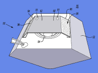
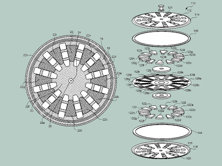
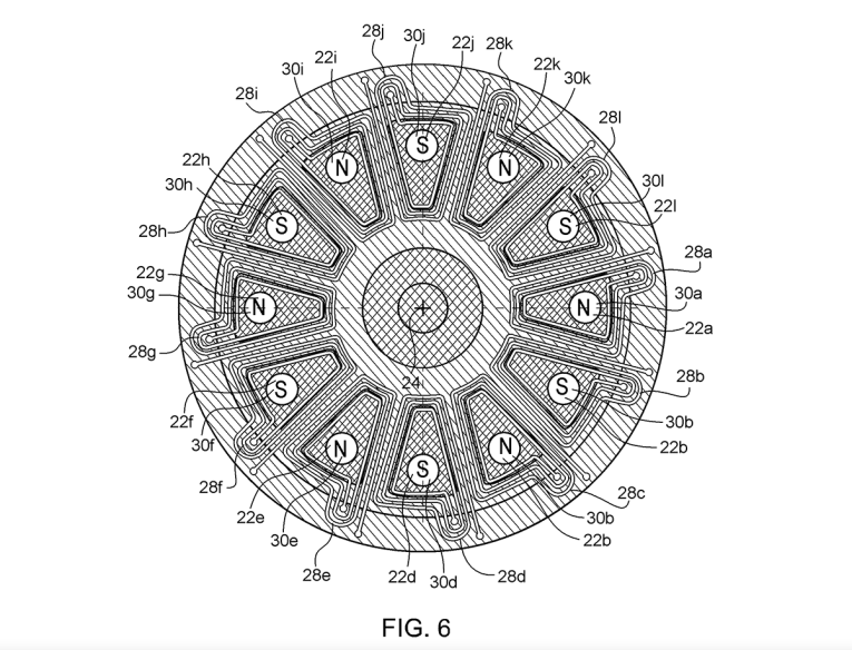
Figure 2 of this patent shows an exploded view of a single-sided drive version of the transducer. Figure 6 of this patent provides a good front surface view of a single-sided drive version of the transducer with the front cover plate removed.
Figure 6 of the patent shows an example of the diaphragm 26 having the conductive traces 28a-28l as well as the first set of the plurality of magnets 22a-22l. Generally, the magnets 22a-22l are placed adjacent to the diaphragm such that they have borders that generally define the open space 30a-30l and are aligned with of each of the respective conductive traces 28a-28l. The traces 28a-28l are around the outside edge of magnets, 22a-22l but the inner circle of trace may overlap with edge of a magnet due to the strong magnetic flux intensity field.
Each of the magnets 22a-22l may be aligned to have a polarity — north (N) or south (S) — facing the diaphragm 26 that is opposite an adjacently positioned magnet. Thus, a magnet has a reversed polarity when compared to the magnets positioned on either side. During operation, the magnets positioned around the diaphragm 26 cause opposing attraction and repulsion of the traces and therefore the diaphragm, as the program signal’s polarity alternates.
A double-sided drive version of the device would be essentially the same, but with another set of magnets mounted opposed on the opposite side of the diaphragm in a manner mirroring the first side magnets, with opposing magnets being of the same polarity. It appears that a significant amount of the area of the diaphragm’s central portion is both undriven and clamped by central clamping ring 24.
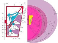
Figure 1 of the patent shows the rather sparse set of openings leaves a significant amount of remaining closed-off surface area, which blocks any radiation from the central portion of the transducer and also blocks more than 50% of the remaining area around the center. The sparse openings and lack of central radiation source may limit dispersion at high frequencies, causing the device to operate as a type of discontinuous ring source, which usually has greater directivity (less dispersion) than a solid flat or dome source.
The patent document does not disclose or illustrate any measurements of directivity or frequency response. It would appear that unless the device is built to a very small diameter, the high-frequency response will most likely not be very useful, particularly in an automotive application where wideband dispersion is most often desired since most listeners are positioned well off-axis.
Besides concerns about high-frequency response and directivity, the device also appears to require that a significant amount of the diaphragm’s central portion remain stationary and unavailable for contribution to the total acoustic output. This would make the total active surface area similar to that of a conventional rectangular or square planar magnetic transducer with a circular mounting frame.
While the directivity would at least be symmetrical at all equal off-axis angles, it is not exactly clear what other, if any, advantages the transducer architecture would provide. But, it is definitely possible that further concept refinement may be able to address some of the shortcomings of the embodiments as disclosed, increasing active surface area and providing a more ideal directivity. VC
This article was original published in Voice Coil, April 2015.