Single-Ended Planar-Magnetic Speaker
US Patent Number: 7142688
www.freepatentsonline.com/7142688.pdf
Inventors: David Graebener (Carson City, NV) and
James J. Croft, III (Poway, CA)
Assignee: American Technology Corp. (San Diego, CA)
Filed: January 22, 2001
US Classes: 381/431
Granted: November 28, 2006
Number of Claims: 62
Number of Drawings: 24
Abstract from Patent
A planar-magnetic electroacoustic transducer including a support structure and a magnetic structure carried by the support structure, the magnetic structure comprising a multiplicity of high-energy magnets configured so as to have shared loop field maxima and local loop field maxima, and a diaphragm carried by the support structure, comprising a plurality of conductors carried by and coupled to the diaphragm, said conductors being disposed in relation to local loop maxima and configured to exploit the energy of local loop maxima, as well as the energy of shared loop maxima in driving the diaphragm to produce an acoustic output; and the magnetic structure can be configured so that it includes magnet rows, and the transverse cross-sectional width of the magnets does not exceed their transverse cross-sectional height, and the distance between adjacent elongated magnet rows is greater than one half the width of either of the magnets of the adjacent magnet rows.
Independent Claims
1. A planar-magnetic transducer comprising: at least one thin film vibratable diaphragm with a first surface side and a second surface side, including a predetermined active region, said predetermined active region including a predetermined conductive surface area for converting an input electrical signal into a corresponding acoustic output; primary magnetic structure including at least three elongated magnets placed adjacent and substantially parallel to each other with said magnets being of high energy and each having an energy product of greater than 25 mega Gauss Greased, which results in strong interaction between adjacent magnets; and a mounting support structure coupled to the primary magnetic structure and the diaphragm to capture the diaphragm, hold it in a predetermined state of tension and space it at a predetermined distance from the primary magnetic structure adjacent one of the surface sides of the diaphragm; said conductive surface area including elongate conductive paths running substantially parallel to said magnets; the mounting support structure, the at least three magnets of the primary magnetic structure, and the diaphragm having coordinated compositions and being cooperatively configured and positioned in predetermined spaced apart relationships wherein (i) the mounting support structure stabilizes the diaphragm in a static configuration at the predetermined tension which remains stable over and between extended periods of use, despite occurrence of dynamic conditions in response to extreme high energy forces driving the diaphragm to audio output, and (ii) the high energy magnetic forces interacting between the at least three magnets do not interfere with the predetermined tension of the diaphragm; said planar-magnetic transducer being operable as a single-ended planar-magnetic transducer.
35. A planar-magnetic transducer comprising: at least one thin film vibratable diaphragm with a first surface side and a second surface side, including a predetermined active region, said predetermined active region including a predetermined conductive surface area for converting an input electrical signal into a corresponding acoustic output; a magnetic structure including at least three elongated magnet rows placed adjacent and substantially parallel to each other with said magnets each being of high energy product greater than 25 mega Gauss Quested; and a mounting support structure coupled to the primary magnetic structure and the diaphragm to capture the diaphragm, hold it in a predetermined state of tension and space it at a predetermined distance from the primary magnetic structure adjacent one of the surface sides of the film diaphragm; said conductive surface area including elongate conductive paths running substantially in parallel with said magnets; the mounting support structure, the diaphragm and the at least three magnets of the primary magnetic structure having coordinated compositions and being cooperatively configured and positioned in predetermined spaced apart relationships wherein (i) the mounting support structure stabilizes the static and dynamic relationship between the diaphragm and the primary magnetic structure over and between extended periods of use and (ii) concurrently resists the high energy magnetic forces interacting between the at least three magnets which would otherwise interfere with the predetermined tension of the diaphragm; said planar-magnetic transducer being operable as a single-ended planar-magnetic transducer.
38. A planar-magnetic transducer comprising: at least one thin film vibratable diaphragm with a first surface side and a second surface side, including a predetermined active region, said predetermined active region including a predetermined conductive surface area for converting an input electrical signal into a corresponding acoustic output; a mounting support structure coupled to the primary magnetic structure and the diaphragm to capture the diaphragm, hold it in a predetermined state of tension and space it at a predetermined distance from the primary magnetic structure adjacent one of the surface sides of the film diaphragm; and primary magnetic structure including at least three high energy, elongated magnets placed adjacent and substantially parallel to each other with each magnet having an energy product of greater than 25 mega Gauss Oersteds (MGO); said conductive surface area including elongate conductive paths running substantially in parallel with said magnets; the mounting support structure, the diaphragm and the at least three magnets of the primary magnetic structure being cooperatively configured and positioned in predetermined spaced apart relationships; at least two of said high energy magnets being adjacently positioned in a predetermined spaced apart relationship wherein adjacent poles of the adjacent magnets have non-shared, localized magnetic loops represented by local loop energy maxima in a plane of the diaphragm which are respectively greater than a shared energy maxima at a central position between the adjacent poles and extending along a shared magnetic loop of the respective adjacent poles in the plane of the diaphragm; said planar-magnetic transducer being operable as a single-ended planar-magnetic transducer.
55. A planar-magnetic transducer comprising: at least one thin film vibratable diaphragm with a first surface side and a second surface side, including a predetermined active region, said predetermined active region including a predetermined conductive surface area for converting an input electrical signal into a corresponding acoustic output; primary magnetic structure including at least three elongated magnets placed adjacent and substantially parallel to each other with at least one of said magnets being of high energy with each having an energy product of greater than 25 mega Gauss Greased; and a mounting support structure coupled to the primary magnetic structure and the diaphragm to capture the diaphragm, hold it in a predetermined state of tension and space it at a predetermined distance from the primary magnetic structure adjacent one surface side of the film diaphragm; said conductive surface area including elongate conductive paths running substantially in parallel with said magnets; any of the at least three adjacent magnets being oriented to be of opposite polarity orientation in relation to an adjacent magnet; said primary magnetic structure having at least three adjacent rows of side by side magnets with at least an outer two rows of the at least three rows of magnets providing less magnetic field strength through the conductive surface area of the diaphragm than provided through the conductive surface areas of the diaphragm by a center row of the magnets; said planar-magnetic transducer operating as a single-ended planar-magnetic transducer.
59. A planar-magnetic transducer comprising: at least one thin film vibratable diaphragm with a first surface side and a second surface side, including a predetermined active region, said predetermined active region including predetermined, elongate conductive surface areas formed of a plurality of conductive elements for converting an input electrical signal into a corresponding acoustic output; a mounting support structure coupled to the primary magnetic structure and the diaphragm to capture the diaphragm, hold it in a predetermined state of tension and space it at a predetermined distance from the primary magnetic structure adjacent one of the surface sides of the film diaphragm; and primary magnetic structure including at least three high energy, elongated magnets placed adjacent and substantially parallel to each other with each magnet having an energy product of greater than 25 mega Gauss Oersteds (MGO); at least two of said high energy magnets being adjacently positioned in a predetermined spaced apart relationship wherein adjacent poles of the adjacent magnets have non-shared, localized magnetic loops represented by local loop energy maxima as well as shared magnetic loops between the respective adjacent poles of the high energy magnets; said conductive surface area running substantially parallel to said magnets and more proximate to the local loops of the high energy magnets than to a center point of the shared magnetic loops between the adjacent magnets; said planar-magnetic transducer being operable as a single-ended planar-magnetic transducer.
Single-End Planar Magnetic Speaker
US Patent Number: 7251342
www.freepatentsonline.com/7251342.pdf
Inventor: David Graebener (Carson City, NV)
Assignee: American Technology Corp. (San Diego, CA)
Filed: March 2, 2001
US Classes: 381/431
Granted: July 31, 2007
Number of Claims: 19
Number of Drawings: 17
Abstract from Patent
A single-end planar magnetic speaker system having at least one thin film, flexible diaphragm (72, 90) having a front side and a rear side for converting an input electrical signal into a corresponding acoustic output, the at least one diaphragm including a predetermined conductive region (76) and a predetermined nonconductive region; a magnetic structure (92) utilizing non-ferrite high energy magnets of a predetermined thickness wherein the magnets are each at least as wide as they are deep; the magnets having a magnetic strength wherein when compared to magnets of a ferrite type of same width as the non-ferrite high energy magnets but which have increased depth to yield at least nearly the same magnetic strength as the high energy magnets in the magnetic structure, doubling the depth of the high energy magnets in the magnetic structure, doubling the depth of the high energy magnets in the magnetic structure yields an increase in speaker sensitivity of at least 3 dB while the doubling the depth of the ferrite type magnet will yield a gain of less than 3 dB, and the system further includes a mounting structure coupled to the diaphragm to capture the diaphragm, to hold it in a predetermined state of tension and space it at a predetermined distance from the magnetic structure.
Independent Claims
1. A single-end planar magnetic loudspeaker system comprising: at least one thin-film, flexible diaphragm having a front side and a rear side, configured for converting an input electrical signal into a corresponding acoustic output, said at least one diaphragm including a conductive material carried by the diaphragm in a predetermined conductive region and a predetermined non-conductive region and a total vibratable surface area of less than 150 in2; at least one high energy magnetic structure of predetermined thickness positioned adjacent to said at least one thin-film, flexible diaphragm, adjacent one but not the other of the front side and the rear side of said diaphragm so as to provide a single-ended transducer configuration, and wherein the high energy magnetic structure is at least 0.060” in thickness and operable to provide a speaker sensitivity of at least 85dB at a power level of 1W; and wherein said predetermined thickness does not exceed a thickness where at least a 3dB increase in SPL is obtained over that which would be obtained in a structure of half said thickness, and is configured in up to seven rows of magnetic material, each of said rows having a cross sectional configuration wherein the width of the material is at least as great as the width thereof; a mounting structure configured as part of the single end planar magnetic speaker and coupled to the diaphragm to capture the diaphragm, hold it in a predetermined state of tension and space it at a predetermined distance from the high energy magnetic structure, and, the system as thus configured being operable as a single-end loudspeaker system.
7. A planar magnetic loudspeaker comprising: a diaphragm of thin, tensionable film including a conductive region and a non-conductive region; a magnetic structure positioned adjacent and at a predetermined distance from said diaphragm for interaction with the conductive region of the diaphragm; a collapsible speaker frame with a plurality of spring biased mounting arms for attachment of the diaphragm at the predetermined distance, said mounting arms having a first, static position at rest, and a second, tensioned position wherein a distance between the mounting arms in the tensioned position is less than a separation distance in the static position and corresponds to a predetermined tension to be applied to the diaphragm during use; means for permanently attaching the diaphragm to the mounting arms of the speaker frame.
8. A single-end planar-magnetic electroacoustic transducer, including: a support structure; a magnetic structure comprising high-energy magnet material arranged in up to seven rows, wherein each row has a cross-sectional shape wherein the width is at least as great as the height; a diaphragm carried by the support structure, having a vibrateable surface area of less than 150 in2; a conductive element carried by and coupled to the diaphragm so that movement of the conductive element moves the diaphragm, positioned with respect to and cooperating with the magnetic structure so that when an appropriate electrical signal is passed through the conductive element, an acoustic output results; the transducer being configured as a single end device and having a sensitivity of at least 85 dB at 1 W in midrange and upper frequency ranges.
13. A single-end planar-magnetic loudspeaker, comprising: a support structure formed primarily of a stamped plate comprising ferrous material; a magnetic structure having up to seven rows of magnets carried by the support structure and cooperating therewith to produce magnetic fields, the magnetic structure including high energy magnets having an energy product of greater than 25 mega-gauss oersteds (MGO), said magnet rows being configured so that in cross section they are at least as wide as they are deep, and are less deep than a depth that when doubled would yield a 3 dB increase in loudspeaker sensitivity all other factors being unchanged, a spacing distance between said rows being at least as great as the depth of the magnetic structure; a thin film, tensioned, diaphragm, carried by the support structure, and which has a composition that includes a polymeric material that can shrink when exposed to electromagnetic radiation; and, a conductive element, carried by and attached to the diaphragm at the conductive area so that movement of the conductive element moves said diaphragm, the conductive element being positioned in a magnetic field adjacent said magnetic structure, the loudspeaker being operable as a single-end planar-magnetic loudspeaker in at least the midrange and upper frequency ranges.
15. A single-end planar-magnetic electroacoustic transducer, comprising: a support structure; a magnetic structure, carried by the support structure, configured to create magnetic fields; a diaphragm comprising PEN material carried by the support structure having a conductive area and a non-conductive area; a conductive element attached to the diaphragm over the conductive area, and positioned within said magnetic fields, configured to cooperate with the magnetic structure to produce forces on the diaphragm when an appropriate electrical signal is passed through the conductive element, whereby an acoustic output is facilitated; wherein the support structure comprises a ferrous material and is configured to enhance the strength of the magnetic fields provided by the magnetic structure, and wherein the magnetic structure comprises a high-energy magnetic material, having an energy product of greater than 25 MGO and comprising neodymium, and wherein the conductive element comprises a conductive material having a high conductivity per volume weight and includes aluminum.
18. A single-end planar-magnetic electro-acoustic transducer, comprising a support structure a high-energy magnetic structure carried by the support structure a tensioned thin-film diaphragm, carried by the support structure, the diaphragm being damped to mitigate unwanted vibration, facilitating improved fidelity of sound reproduction; a conductive element carried by and attached to the diaphragm; the forgoing cooperating so that when an appropriate electrical signal is sent through the conductive element forces are created acting through the conductive element on the diaphragm, causing movement of the diaphragm which results in an acoustic output; wherein the diaphragm has material applied thereon, which facilitates damping of the diaphragm.
Reviewer Comments
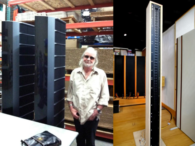
The two patents under review are the first and second of the Single-Ended, Neodymium Planar Magnetic Transducer patents granted to the late David Graebener. Prior to the time period that David invented these devices, planar magnetics were substantially relegated to small high-frequency devices, large surface area wider bandwidth systems (e.g., Jim Winey’s Magneplanars) or very low efficiency devices. With the introduction of practical, cost-effective, high-energy neodymium iron magnet material, there was an opportunity to develop a wider bandwidth planar magnetic transducer of a more modest size that also achieved reasonable efficiency.
Around the same time, Bruce Thigpen developed a neodymium-based planar magnetic device (US Patent 5,901,235) configured as a double-ended, push-pull architecture, with virtual magnetic poles between each magnet. But, as with most double-ended planar magnetic transducers, the high-frequency response above 7kHz is compromised due to acoustical problems caused by cavity effects between the magnet rows. David Graebener wanted to develop wide bandwidth devices with extended high frequencies, so he capitalized on the high-energy magnets to optimize output while extending smooth high frequency response beyond 30kHz with a single-ended planar architecture with one open side. Within the two patent cases numerous sub-inventions and attributes are disclosed for the single-ended neodymium based planar magnetic transducers.
When first applying high-energy neodymium magnets to a single-ended planar device the greater magnet strength could cause problems as the adjacent, parallel rows of opposite polarity magnets are attracted to each other with very high force. A key issue with thin film transducers, such as planar magnetics or electrostatics, is to establish and maintain ideal diaphragm tension.
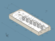
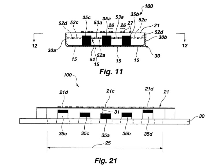
When using a magnetically conductive steel backplane that is as thin as possible to achieve low cost while being just thick enough to avoid magnetic saturation, the magnetic forces can cause the magnet rows to attract, which in turn would cause the back plate to bend. This would decrease the tension of the film diaphragm, allowing the diaphragm to buzz and distort during operation. So, one aspect of the invention was to provide several solutions to the problem, including inter-magnet bracing struts as shown in Figure 11 of the patent, a front cover-brace combination, and other ways to maintain structural integrity and constant diaphragm tension over time.
A second aspect of the invention was to incorporate an inter-magnet brace that is made of copper to both provide frame stability and also to reduce inductance modulation distortion. A third aspect of the invention was to make more efficient/lower-cost use of the magnetic material. Starting with the idea that the diaphragm of planar film transducers operate as a tympanic device, with greater excursion in the center and less excursion for diaphragm areas away from the center, as opposed to standard isotonic diaphragm transducers. Since during high excursions the diaphragm displacement is greater in the center that is where the greater gap is required between the magnet surface and the diaphragm.
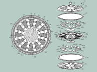
Whereas, farther away from the center of diaphragm a magnet row is placed, the magnets can be moved closer to the diaphragm surface as shown in Figure 21 of the patent. Also, because they are closer, their magnetic coupling will be more efficient, so the outer magnets can also be smaller for a given local BL. As can be seen in the drawing, smaller and closer coupled magnets can be used at the outer portion of the mobile and conductive portion of the diaphragm.
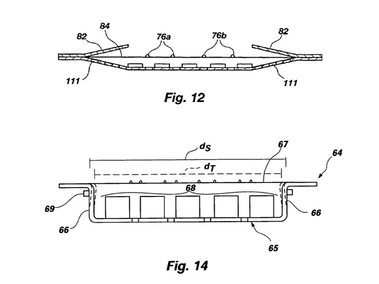
A fourth aspect of the invention, disclosed in the second case, is that of using spring steel as the back plate-frame structure such that the side-wall portions of the frame can be bent inward to capture the film, then once the film is attached, the frame is released and expands to apply a predetermined amount of spring tension to the diaphragm.
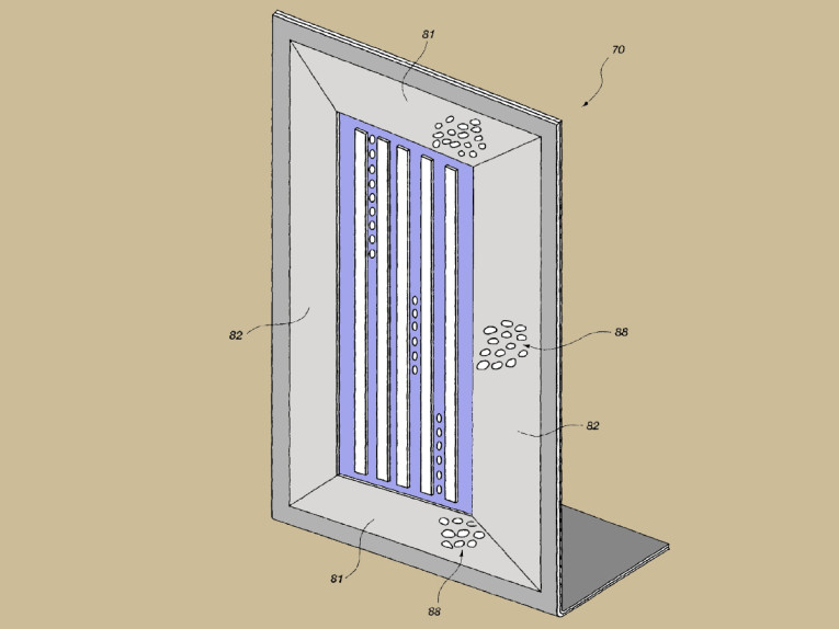
Additional aspects of the invention relate to optimizing magnetic bar height-to-width form factor for the most efficient use of the neodymium material, and front-side frame flanges in close proximity to the outer area of the diaphragm to load and control the undriven portion of the diaphragm and to create a dispersion lens for the device to sustain more constant dispersion at higher frequencies. Further aspects of the invention are disclosed in the patent to optimize the various components, processes, and fabrication techniques.
The combination of the disclosures within the patents, combined with several trade secret aspects that David Graebener developed over the years, has resulted in several high-performance planar magnetic systems—from small multimedia devices to large scale, wide-bandwidth systems. These systems are just a small part of the extensive legacy of innovation that David Graebener has left for posterity. VC
This article was originally published in Voice Coil, March 2015