The two patents listed for this month’s patent reviews are derived from the same original Provisional filing and disclosure material. They are essentially for the same invention, but after the first patent was granted, the inventor/assignee filed for a continuation case, wherein they use the same specification and drawings, but broaden their claims.
Often in patent filings, the inventor and their attorney will put in claims that have a greater chance of being granted, by including a combination of many elements, to differentiate from any prior art. Once that case is granted, then the inventor can file a continuation case with broader claims that has few elements, and makes it harder for any infringers to do a work around by changing only one element. That is the case here where the main difference in the later patent, is that the claims are shorter and broader, with the elements in the claims of the first case now spread over multiple claims, which are each simpler and broader, offering greater patent protection for the same invention.
Speaker Device
Patent Number: 8,139,813
Inventors: Kobayashi; Hiroyuki (Tendon, Japan), Haiti; Toshihiro (Tendon, Japan), Origami; Minoru (Tendon, Japan), Abe; Yasuhisa (Tendon, Japan)
Assignee: Pioneer Corp. (Tokyo, Japan), Tohoku Pioneer Corp. (Yamagata, Japan)
Filed: January 28, 2008
Current US Class: 381/398
Current CPC Class: H04R 9/10 (20130101)
Granted: March 20, 2012
Number of Claims: 21
Number of Drawings: 17
Abstract from Patent
A flat speaker device capable of emitting loud reproduced sound with a relatively simple configuration is provided. The speaker device includes a diaphragm, a frame supporting the diaphragm veritably in the vibration direction, a magnetic circuit disposed in the frame, and a driving member for driving the diaphragm. The driving member includes a voice coil movably disposed in a magnetic gap of the magnetic circuit, a driving part formed movably in a direction different from the vibration direction of the diaphragm, and an angle conversion and transmission part, one end of which is angle-variably joined to the driving part and another end of which is angle-variably joined to the diaphragm. The angle conversion and transmission part has rigidity and is obliquely disposed with respect to each of the vibration direction of the diaphragm and the moving direction of the driving part.
Independent Claims
1. A speaker device comprising: a diaphragm; a frame supporting the diaphragm veritably in a vibration direction of the diaphragm; a magnetic circuit disposed in the frame; and a driving member adapted to drive the diaphragm, wherein the driving member comprises: a driving part comprising a voice coil movably disposed in a magnetic gap of the magnetic circuit, wherein the driving part is formed movably in a direction different from the vibration direction of the diaphragm; and a rigid angle conversion and transmission part, wherein one end of the rigid angle conversion and transmission part is angle-variably joined to the driving part, wherein another end of the rigid angle conversion and transmission part is angle-variably joined to the diaphragm, and wherein the rigid angle conversion and transmission part is obliquely disposed with respect to each of the vibration direction of the diaphragm and the moving direction of the driving part.
Speaker Device
Patent Number: 8,457,344
Inventors: Kobayashi; Hiroyuki (Tendon, Japan), Haiti; Toshihiro (Tendon, Japan), Origami; Minoru (Tendon, Japan), Abe; Yasuhisa (Tendon, Japan)
Assignee: Pioneer Corp. (Tokyo, Japan), Tohoku Pioneer Corp. (Yamagata, Japan)
Filed: October 13, 2011
Current US Class: 381/406
Current CPC Class: H04R 9/10 (20130101)
Granted: June 4, 2013
Number of Claims: 23
Number of Drawings: 17
Abstract from Patent
A flat speaker device capable of emitting loud reproduced sound with a relatively simple configuration is provided. The speaker device includes a diaphragm, a frame supporting the diaphragm veritably in the vibration direction, a magnetic circuit disposed in the frame, and a driving member for driving the diaphragm. The driving member includes a voice coil movably disposed in a magnetic gap of the magnetic circuit, a driving part formed movably in a direction different from the vibration direction of the diaphragm, and an angle conversion and transmission part, one end of which is angle-variably joined to the driving part and another end of which is angle-variably joined to the diaphragm. The angle conversion and transmission part has rigidity and is obliquely disposed with respect to each of the vibration direction of the diaphragm and the moving direction of the driving part.
Independent Claims
1. A speaker device comprising: a diaphragm; a magnetic circuit; a driving member; and a frame supporting a magnetic circuit, wherein said driving member comprises: a voice coil; and a rigid angle conversion and transmission part connected with said voice coil and said diaphragm via a folding part, wherein a vibration direction of said voice coil is different from a vibrating direction of said diaphragm, wherein said rigid angle conversion and transmission part is arranged in a direction different from said vibration direction of voice coil and said vibrating direction of diaphragm.
12. A speaker device comprising: a diaphragm; a magnetic circuit; a driving member; and a frame supporting a magnetic circuit, wherein said driving member comprises: a voice coil; and a rigid angle conversion and transmission part connected with said voice coil and said diaphragm via a bending part, wherein a vibration direction of said voice coil is different from a vibrating direction of said diaphragm, wherein said rigid angle conversion and transmission part is arranged in a direction different from said vibration direction of voice coil and said vibrating direction of diaphragm.
13. A speaker device comprising: a diaphragm; a magnetic circuit; a driving member; and a frame supporting a magnetic circuit, wherein said driving member comprises: a voice coil; and a rigid angle conversion and transmission part angle-variably connected with said voice coil and said diaphragm, wherein a vibration direction of said voice coil is different from a vibrating direction of said diaphragm, wherein said rigid angle conversion and transmission part is arranged in a direction different from said vibration direction of voice coil and said vibrating direction of diaphragm.
22. A speaker device comprising: a diaphragm; a magnetic circuit; a driving member; and a frame supporting a magnetic circuit, wherein said driving member comprises: a voice coil; and a rigid angle conversion and transmission part connected with said voice coil and said diaphragm via a folding part, wherein a vibration direction of said voice coil is different from a vibrating direction of said diaphragm, wherein said rigid angle conversion and transmission part converts an angle of said vibration of voice coil and transmits said vibration of voice coil to said diaphragm.
23. A speaker device comprising: a diaphragm; a frame supporting said diaphragm in a vibration direction of said diaphragm; a magnetic circuit disposed in said frame; and a driving member adapted to drive said diaphragm, wherein said driving member comprises: a voice coil disposed in a magnetic gap of said magnetic circuit and, a rigid angle conversion and transmission part, wherein said vibration direction of said voice coil is different from the vibration direction of said diaphragm, a rigid angle conversion and transmission part is angle-variable to said driving member and said diaphragm, wherein one end of said rigid angle conversion and transmission part is connected to said driving part, wherein another end of said rigid angle conversion and transmission part is connected to said diaphragm, and wherein said rigid angle conversion and transmission part is obliquely disposed with respect to each of said vibration direction of diaphragm and said vibration direction of voice coil.
Reviewer Comments
As has always been the case, loudspeaker engineers have sought to reduce the size of low-frequency systems. Historically, there have been two primary dimensions of reduction in size — that of enclosure volume and driver size. While enclosure volumes have been stubbornly bound by Hofmann’s Iron Law, woofer cone area has been able to be substantially reduced as new motors and suspension systems have made large excursions possible and practical.
Unfortunately, to reduce driver cone area in exchange for increased driver excursion, transducer front-to-back depth has substantially increased, limiting the packaging advantages of a device with a smaller faceprint. With the advent of flat-panel TV monitors and restricted space availability for woofers in vehicles, shallow woofer structures have become desirable. With conventional architectures, that would tend to require a reduction in excursion capability.
While there have been a number of shallow woofer structures attempting to address this issue such as US 9,467,783, “Low profile loudspeaker transducer,” by George Bullimore, assigned to Tymphany, they are usually limited to Xmax values that are 6 mm or less, to maintain the low profile.
Another solution, utilizing a number of interconnected small cone diaphragms aligned coaxially, is US 9,462,388, by Andrew David Unruh, et al, assigned to Tymphany HK, Ltd. This approach converts mechanical movement in one axis to acoustical output at a 90° angle to the mechanical axis of motion. The system is based on the novel developments of the brilliant Oskar Heil in the 1970s, where he applied his well-known Air Motion Transformer (AMT) technology to the lesser known, and short lived (due to reliability issues), AMT woofer systems, disclosed in US 4,039,044 and US 4,107,479. For those interested, the Great-Grand Daddy of this concept was invented in 1914 by Charles Chudzikkowski and disclosed in US 1,273,459, “Soundboard.”
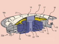
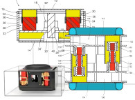
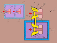
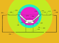
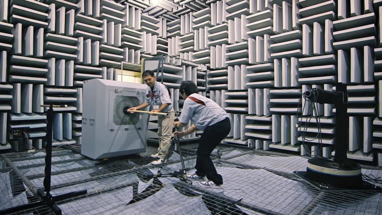
The current Pioneer patents under review represent an ambitious effort, taking the “acoustic right-angle” approach of Unruh and Heil a step further by creating a mechanical structure that converts a linear voice coil motion in one axis to an orthogonal mechanical diaphragm displacement (see Photo 1). The system functions much like a scissor-jack you would use to raise your automobile to change a tire. The linear motion of the threaded rod coverts the axial force to a 90° lift movement.

A person is usually not concerned about the noise, mass, or friction of the moving parts of a scissor-jack. However, in a woofer system these parameters are of particular consideration, albeit the moving mass is somewhat less important when operating at low frequencies in miniature enclosure volumes, where an increase may be desirable to achieve a low resonant frequency even with the resulting sacrifice of a commensurate reduction in efficiency.
Relative to conventional woofers, the actual production device is a sophisticated, precision work of art, with a complex set of pivot bearings and struts as an intermediate structure between the voice coil and the mobile diaphragms.
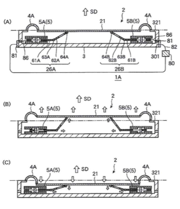
While the patent only addresses a single diaphragm system, the actual production unit comprises two opposed diaphragms, cyclically moving apart on a positive signal and toward each other on a negative signal. This turned out to be the most effective structure that also provides a balanced, low vibration device.
Additional information about Pioneer’s TS-WH500A subwoofer based on this concept and a simulation of the device in operation can be seen in the YouTube video at: www.youtube.com/watch?v=oWfLaGklYxQ
In operation, the amount of voice coil excursion is comparable to the amount of diaphragm excursion. When realizing this type of system, others have attempted to further advance the mechanical translating structure to incorporate a mechanical lever to transform “X” amount of voice coil excursion into “2X” diaphragm displacement. This is similar in concept to what Philips explored in the early 1980s and disclosed in US 4,547,631, wherein they used a standard format woofer system, but with a mechanically pivoted lever between the voice coil and woofer diaphragm. If you think of a lever where one is attempting to lift a heavy object, if, as per convention, one pushes on the long end, reduced force is required, but the object is not moved as far as it would be if both sides of the lever were equal. Incorporating leverage in an electro-acoustical transduction system operates as if one is pushing on the short end of the lever, increasing the diaphragm displacement as compared to the voice coil placement. Unfortunately, the diaphragm mass reflected through the “lever” is increased and the electro-magnetic force (Bl) requirements can quickly increase beyond practical limits and, therefore, the “lever” technique has not been found to be a useful solution for increased transducer excursion capability.
Ultimately, the Pioneer system based on these patents is an interesting and novel way to realize significant excursion capability in a thin form factor package. It will be interesting to see if it is a cost-competitive system as compared to less complex alternative structures attempting to achieve the same packaging and displacement advantages. It is always gratifying to see an audio company that is both capable and determined enough to realize such an interesting device as a practical production system. VC
This article was originally published in Voice Coil, Januray 2018.