Title: Low Profile Loudspeaker Device
Patent Publication Number: US11,297,415
Inventors: Mattias Jeffrey Scheek (Amsterdam, NL); Timothy Ruben Scheek (Amsterdam, NL)
Assignee: Mayht Holding B.V.
Filed: October 26, 2018
Current International Classes: H04R 1/28 (20060101); H04R 9/04 (20060101); H04R 9/06 (20060101);
H04R 7/04 (20060101)
Granted/Published: April 5, 2022
Number of Claims: 16
Number of Drawings: 9
Abstract from Patent
A loudspeaker device comprises first and second diaphragms (12, 14) arranged co-axially in an opposed relation to each other to cancel mechanical vibrations. Each diaphragm has multiple voice coils, with the voice coils of the first and second diaphragms (12, 14) arranged in the same plane to reduce the height of the loudspeaker device.
Independent Claims
1. A loudspeaker device, comprising: first and second diaphragms arranged co-axially in an opposed relation to each other and having a rear volume in-between, each diaphragm having a plurality of motors operatively coupled thereto, wherein the motors of the first and second diaphragms are arranged in the same plane, wherein the frame comprises first and second rims provided at the first and second ends, respectively, wherein the first diaphragm is mounted to the first rim via a first surround, and the second diaphragm is mounted to the second rim via a second surround, wherein the frame further comprises a plurality of struts extending between the first and second rims, the motors being provided on the struts.
Reviewer Comments
Due to the multi-faceted aspects of both the technology and performance claims involved, we will be presenting the patent reviews for this concept as a multi-part story that will appear in the next several issues of Voice Coil.
Just over four years ago patent application disclosures of an interesting new transducer format started to appear, invented by two young gentlemen (brothers Mattias and Timothy Scheek) from a company called Mayht Technologies (pronounced “Might”) located in the Netherlands. I continued to follow their work through a number of additional patent publications along with promotional announcements in the audio press that started to appear a little more than 2-years ago, including in our own sister magazine, audioXpress.
The structural designs were unconventional and appeared to represent some fresh thinking. As I continued to follow the patent trail, combined with reading the promotional disclosures, the claims that the company was making were quite bold. Not only were the claims suggesting incremental advancements in one or two parameters, some claims were orders of magnitude improvements over the current state of the art in nearly every significant category. (The technology is presented on the Mayht website at:
www.mayht.com/technology.)
Some of the key claims are (starting from the merely impressive and leading up to the incredible):
- “Perfectly” symmetrical and flat BL due to the Mayht magnetic system
- “Perfectly” symmetrical and flat Kms due to the Mayht spider leg suspension
- Extremely low THD at high output — even in small enclosures
- The world’s first dual-diaphragm, fully balanced (vibration cancelling) transducer
- The same output as a conventional driver with approximately 2.5 times larger cone area (a 3.5” Mayht driver with two diaphragms compared to a standard single diaphragm 8” woofer)
- Five times lighter than a conventional driver with the same maximum output...and lastly, why not take a shot at breaking Hofmann’s Iron Law?
- “Air pressure issue solved” — Enclosure volumes are achieved that are more than 10 times smaller than a conventional system of the same efficiency and low frequency bandwidth.
Normally, when we see this kind of promotion of a new loudspeaker technology, one can usually bet money that an overly eager marketing department has started writing the engineering specifications and the reality is much more down to earth.
While looking at all their patents and visual demonstrations of the transducers in operation, the device does appear that it might at least be a useful format for efficient packaging of smallish systems, but while still feeling some rather deep skepticism about their performance claims, something very interesting happened on April 11… I opened a financial page on the Internet and the headline read: “Sonos (SONO) acquires a Netherlands-based company Mayht Holding, for $100 million in existing cash on hand.”
Now, if a company buys a loudspeaker technology for $100,000, you would expect them to have done a reasonable amount of diligence before financing the purchase, but if a major public company purchases a loudspeaker transducer technology for $100 million dollars with “cash on hand,” then one would expect that the company has performed a very thorough due diligence exercise, and would only consider such a move if the diligence report was commensurate with the kind of claims Mayht has made for its products.
I am familiar with some of the engineers at Sonos, and they are highly skilled individuals with a healthy skepticism, and any transducer boasting these capabilities would have to really perform to get past the likes of these fellows, assuming they were engaged in the diligence process. So, I have to admit, while my doubts were not completely diminished, my curiosity was suddenly magnified significantly.
Then, I went back and reread through all the Mayht patent applications and also searched for some more recently filed Mayht cases that were available in Chinese publications that I ran through a translator.
There are numerous patents that have been filed by the Scheek brothers and the early ones appear to be for single diaphragm versions that were filed before the current concept had been fully conceived. The structural concepts that are disclosed in their published patents appear to currently be split into a few categories:
- Thin, dual-diaphragm transducers with interleaved, cross-coupled motor structures
- Specialized connector systems between the voice coils and the diaphragms
- A different configuration and placement of the centering spiders
- A compliance-enhancing basis for overcoming air spring stiffness in small enclosures
In this first review segment of the multi-part series, we will explore the first patent for the thin, dual-diaphragm transducers with interleaved, cross-coupled motor structures.
Some of the first system dual diaphragms, interleaved motor, concepts that have been shown in the latest devices on their website are disclosed in a 2017 filing, which was granted in April of 2022 as US11,297,415. This is the patent that we will explore here.
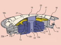
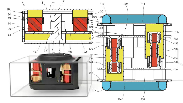
As a first walk through of the basic structure, referring to Figure 1A and Figure 1B, the loudspeaker transducer 10 is illustrated comprising a first diaphragm 12 and a second diaphragm 14 arranged co-axially in an opposed relation to each other. In this embodiment, as with most of the publicized devices, the diaphragms are of a flat, circular form. Between the first and second diaphragms is a shared “rear wave” volume 15.
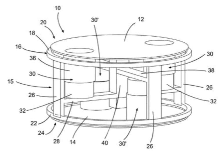

The loudspeaker transducer includes a frame support structure 16 having a first rim 18 located at a first end 20 and a second rim 22 located at a second end 24 of the frame. The first diaphragm 12 is mounted to the first rim 18 via a first surround suspension (not shown) and the second diaphragm 14 may be mounted to the second rim 22 via a second surround suspension (also not shown).
Four vertical beams 26, equally spaced around the perimeter, extend between the first and second rims 18, 22 as part of the frame 16. Cross beams 28 and 38 complete the frame structure 16.
Two motors 30 are mounted on the frame and are coupled to the first diaphragm 12 through their voice coil formers 36, which are spaced apart symmetrically on each side of the diaphragm. Each motor 30 comprises a magnet 32 that is attached to the first support member 28, and a voice coil 34 provided on a former 36. The former 36 of each motor 30 is attached to the first diaphragm 12.
As with the first diaphragm 12, the second diaphragm 14 also has two associated motors 30’ with voice coil formers connected to diaphragm 14.
This configuration results in the motors 30, 30’ of the first and second diaphragms 12, 14 being arranged in the same lateral plane, which minimizes the height of the transducer. As compared to two back-to-back transducers of conventional form, where the height profile would be twice that of a single device, the loudspeaker system of this invention has a claimed height dimension that is only 1.25 times the profile of a single-driver system. Further, to achieve this height reduction, this transducer does not increase the lateral profile compared to a single-driver system since the diaphragms are coaxially aligned. And, operating as an in-phase, bipolar transducer, mechanical vibrations from movement of the diaphragms 12, 14 in use are cancelled due to the opposed configuration of the diaphragms.
It is claimed that using multiple separate motors 30, 30’ for the diaphragms 12, 14 can increase the efficiency, making it possible to reproduce lower frequencies in a small closed cabinet and that attaching multiple motors to each diaphragm may increase linearity and diaphragm rigidity.
Figure 2 shows a transducer of similar configuration to the one shown in Figure 1 but with a large roll surround suspension 117 and elongated motor structures 130, 130’ with multiple magnets 132, 132’ to optimize for larger excursion capability, while still relying on the cross-coupled, interleaved motors to minimize total transducer height for a given excursion capability.
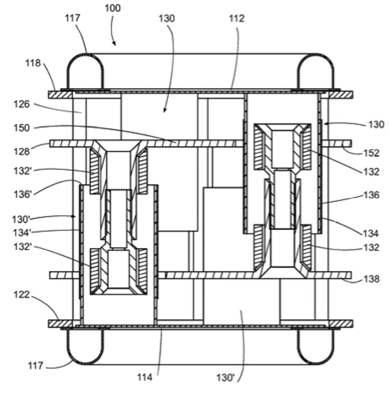
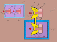
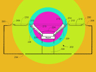
It is claimed that the arrangement of the motors 130, 130’ in the same lateral plane permits a maximum excursion of each diaphragm corresponding to one-third of the height of the transducer. Referring to Figure 3, the invention is shown in a form somewhat closer to the latest embodiments, with the first pair of motors 330 located laterally outside of the diameter of the diaphragm, with struts 360 connecting from the voice coil former 336, of voice coil 334, to the first diaphragm 312.
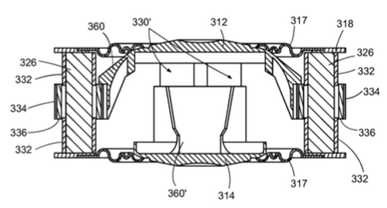
By placing the cross-coupled, interleaved motor structures outside of the diaphragm and surround, the system can provide room for even more excursion without having the front and rear diaphragms and voice coil systems interfering with each other.
While the disclosure shows illustrations of the magnetic structures of the motor assemblies, there is a dearth of text explaining what form these magnetic structures take and how they operate. If one looks at the drawings, and also pictures and videos on the Mayht website, it appears that the motors are substantially void of any focusing elements, such as top plates, and appear to operate from the fringe fields of the magnets themselves. Unless there is some unique interaction between the voice coils and the magnetic system that has not yet been disclosed, it is difficult to see how this motor structure would exhibit the efficiency that is claimed.
In terms of the claim of novelty of being “The world’s first dual-diaphragm, fully balanced (vibration cancelling) transducer,” even limiting the search to those that also have nested, voice coils substantially in the same plane, to provide both vibration cancellation and a shallower package, a quick study will suggest a number of prior art devices as candidates, such as; US6,622,817 “Sound Reproduction Device Working According to the Bending Wave Principle,” invented by Wolfegang Bachmann, et al, and assigned to Harman Audio Electronic Systems GmbH; US6,931,140 “Electro-acoustic Transducer with Two Diaphragms,” invented by Aart Van Halteren and Leif Johannsen, and assigned to Sonionkirk A/S; US7,912,240 “Dual Diaphragm Electroacoustic Transducer,” by Peter Madaffari and Sietse Van Reeuwijk and assigned to Sonion Nederland; along with patent publications on more current and familiar devices, such as the KEF UniCore driver US2021/0227331 “Loudspeakers,” by Jack Oclee-Brown and Christopher Spear, assigned to GP Acoustics International; US10,631,096 “Force Cancelling Transducer,” by Jordi Antoni Garcia Selva, et al, assigned to Apple Inc.; and US11,044,562 “Multi-Diaphragm Speaker Driven by Multiple Voice Coil Plates and a Shared Permanent Magnet Pair,” by Leeg Hyun Cho, et al, assigned to Resonado, Inc.
If there were a novelty of the Mayht device in this regard, it would seem to be more centered on their specific approach to placing the motors and voice coils around the periphery of the device and extending connecting struts from the multiplicity of voice coil formers over to the diaphragm body. While this would seem to be an effective expedient to further minimize package size while achieving large excursions, for many of the “full-range” devices promoted by the company, it would seem to be difficult to maintain good frequency response at high frequencies when using this configuration.
For the best full-range performance, they may need to resort to the more conventional format of having all the voice coils directly coupled to the diaphragms within the inside diameter of the surround suspensions.
In terms of the claims that their 3.5” devices can equal an 8” woofer in low-frequency output, this would require their device to have approximately 2.5 times the excursion capability. It is unclear, so far, as to how their configuration would have the ability to exhibit such a large excursion advantage.
Even with an Xmax of 5mm in a modest standard 8” woofer, the comparative Mayht device would have to achieve an Xmax of at least 12.5mm and for one of the better 8” woofers, with an Xmax of 12mm or more, it would seem that the little 3.5” Mayht device would be reaching excursion levels of over ±30mm or almost 5” peak to peak. A strong claim indeed.
It will be interesting to see if, and how, Mayht has developed specialized surround suspensions and magnetics that can efficiently support those kinds of performance numbers. Ultimately, the new structure is innovative and includes some novel thinking and should be able to perform competitively with the current state of the art. It will remain to be seen if it can best all current loudspeaker technologies to the degree they are claiming it can.
In the next patent review installment, we will delve deeper into additional Mayht patents that explore more aspects of the structures along with even stronger claims, including the most significant of all: The ability to reduce loudspeaker enclosure volumes to 1/10th that of the current state of the art. Stay tuned. VC
This article was originally published in Voice Coil, July 2022