Vertically and Horizontally Balanced Subwoofer
Patent Number: 9,462,391
Inventors: Robert G. Johnston (Amprior Ontario, CA),
Sanford M.Gross (Owings Mills, MD)
Assignee: None listed
Filed: September 23, 2015
Current CPC Class: H04R 1/2834 (20130101)
Granted: October 4, 2016
Number of Claims: 16
Number of Drawings: 7
Abstract from Patent
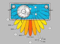
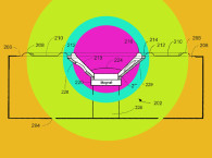
A speaker system, particularly useful as a subwoofer, comprises an enclosure with one acoustic transducer facing to the right and one acoustic transducer facing to the left, which effectively cancels out transducer cone mass induced vibration within the enclosure. The enclosure also has one passive radiator facing up and one passive radiator facing down. The passive radiator facing down effectively couples acoustic energy at very low frequencies into the floor. The passive radiators each have a rather a large area and high mass. The large, high mass, bottom mounted passive radiator will produce large amounts of enclosure vibration, and so to cancel this vibration, the upper passive radiator is of substantially the same mass and size. The resulting system will be vibrationally balanced on all axes while simultaneously effectively coupling low frequency energy onto the floor of the listening room with good efficiency.
Independent Claims
1. A loudspeaker system for having a total mass, the loudspeaker system comprising: a first panel, the first panel defining a first opening, the first opening having a first area; a first opposite panel underneath the first panel and being substantially parallel to the first panel, the first opposite panel defining a first opposite opening, the first opposite opening having a first opposite area, the first area and the first opposite area providing a cumulative passive radiation area; a second panel extending between the first panel and the first opposite panel, the second panel defining a second opening, the second opening having a second area; a second opposite panel extending between the first panel and the first opposite panel, the second opposite panel being substantially parallel to the second panel and being substantially perpendicular to both the first panel and the first opposite panel, the second opposite panel defining a second opposite opening, the second opposite opening having a second opposite area, wherein the second area and the second opposite area provides a cumulative driver radiation area; a third panel extending between the first panel and the first opposite panel, the third panel further extending between the second panel and the second opposite panel; a third opposite panel spaced apart from the third panel, the third opposite panel extending between the first panel and the first opposite panel, the third opposite panel further extending between the second panel and the second opposite panel; an enclosure being comprised of the first panel, the first opposite panel, the second panel, the second opposite panel, the third panel and the third opposite panel; a driver at the second opening of the second panel; an opposite driver at the second opposite opening of the second opposite panel, each of the driver and the opposite driver comprising a magnet voice coil and an active diaphragm with a voice coil, the active diaphragm being driven to move relative to the enclosure in response to an electromagnetic interaction between the magnet and the voice coil, the magnet being substantially fixed relative to the enclosure, the active diaphragm of the driver and the active diaphragm of the opposite driver providing a cumulative active radiator mass; a passive radiator at the first opening of the first panel; and an opposite passive radiator at the first opposite opening of the first opposite panel, each of the passive radiator and the opposite passive radiator comprising a passive diaphragm that is driven pneumatically in reaction to movement of the driver and the opposite driver, the passive diaphragm of the passive radiator and the passive diaphragm of the opposite passive radiator providing a cumulative passive radiator mass, the enclosure having an enclosure mass equal to the total mass of the speaker system minus a combination of both the cumulative active radiator mass and the cumulative passive radiator mass, the driver being substantially equal to the opposite driver, the passive radiator being substantially equal to the opposite passive radiator, and the cumulative passive radiator mass being at least three times greater than the cumulative active radiator mass.
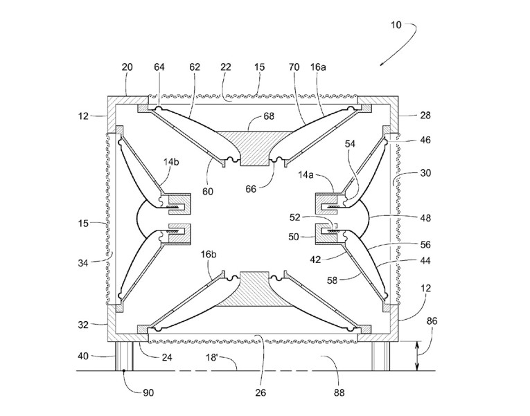
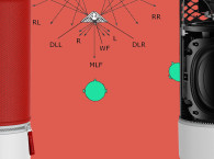
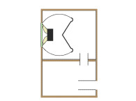
5. A loudspeaker system for use above a supporting surface, the loudspeaker system having a total mass, comprising: a top panel, the top panel defining an upper opening, the upper opening having an upper area; a bottom panel underneath the top panel and being substantially parallel to the top panel, the bottom panel defining a lower opening, the lower opening having a lower area, the upper area and the lower area providing a cumulative passive radiation area, the outer periphery of the lower panel having a total peripheral length, the bottom panel having a footprint defined by an outer periphery of the lower panel, a right panel extending vertically between the top panel and the bottom panel, the right panel defining a right opening, the right opening having a right area; a left panel extending vertically between the top panel and the bottom panel, the left panel being substantially parallel to the right panel and being substantially perpendicular to both the top panel and the bottom panel, the left panel defining a left opening, the left opening having a left area, wherein the right area and the left area provides a cumulative driver radiation area; a front panel extending between the top panel and the bottom panel, the front panel further extending between the right panel and the left panel; a rear panel spaced apart from the front panel, the rear panel extending between the top panel and the bottom panel, the rear panel further extending between the right panel and the left panel; an enclosure being comprised of the top panel, the bottom panel, the right panel, the left panel, the front panel and the rear panel; a spacer extending downward from the enclosure to a lowermost point of the spacer, wherein the lowermost point is on an imaginary plane lying substantially parallel to the bottom panel with a gap defined by a vertical spaced apart distance between the bottom panel and the imaginary plane; a floor coupling area defined as the vertical spaced apart distance times the total peripheral length of the outer periphery of the lower panel; a right driver at the right opening of the right panel; a left driver at the left opening of the left panel, each of the right driver and the left driver comprising a magnet and an active diaphragm with a voice coil, the active diaphragm being driven to move relative to the enclosure in response to an electromagnetic interaction between the magnet and the voice coil, the magnet being substantially fixed relative to the enclosure, the active diaphragm of the right driver and the active diaphragm of the left driver providing a cumulative active radiator mass; an upper passive radiator at the upper opening of the top panel; and a lower passive radiator at the lower opening of the bottom panel, each of the upper passive radiator and the lower passive radiator comprising a passive diaphragm that is driven pneumatically in reaction to movement of the right driver and the left driver, the passive diaphragm of the upper passive radiator and the passive diaphragm of the lower passive radiator providing a cumulative passive radiator mass, the enclosure having an enclosure mass equal to the total mass of the speaker system minus a combination of both the cumulative active radiator mass and the cumulative passive radiator mass.
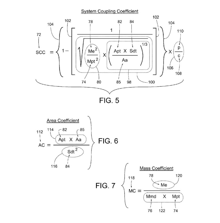
11. A loudspeaker system for use above a supporting surface, the loudspeaker system having a total mass, comprising: a top panel, the top panel defining an upper opening, the upper opening having an upper area; a bottom panel underneath the top panel and being substantially parallel to the top panel, the bottom panel defining a lower opening, the lower opening having a lower area, the upper area and the lower area providing a cumulative passive radiation area, the outer periphery of the lower panel having a total peripheral length, the bottom panel having a footprint defined by an outer periphery of the lower panel, a right panel extending vertically between the top panel and the bottom panel, the right panel defining a right opening, the right opening having a right area; a left panel extending vertically between the top panel and the bottom panel, the left panel being substantially parallel to the right panel and being substantially perpendicular to both the top panel and the bottom panel, the left panel defining a left opening, the left opening having a left area, wherein the right area and the left area provides a cumulative driver radiation area; a front panel extending between the top panel and the bottom panel, the front panel further extending between the right panel and the left panel; a rear panel spaced apart from the front panel, the rear panel extending between the top panel and the bottom panel, the rear panel further extending between the right panel and the left panel; an enclosure being comprised of the top panel, the bottom panel, the right panel, the left panel, the front panel and the rear panel; a spacer extending downward from the enclosure to a lowermost point of the spacer, wherein the lowermost point is on an imaginary plane lying substantially parallel to the bottom panel with a gap defined by a vertical spaced apart distance between the bottom panel and the imaginary plane; a floor coupling area defined as the vertical spaced apart distance times the total peripheral length of the outer periphery of the lower panel; a right driver at the right opening of the right panel; a left driver at the left opening of the left panel, each of the right driver and the left driver comprising a magnet and an active diaphragm with a voice coil, the active diaphragm being driven to move relative to the enclosure in response to an electromagnetic interaction between the magnet and the voice coil, the magnet being substantially fixed relative to the enclosure, the active diaphragm of the right driver and the active diaphragm of the left driver providing a cumulative active radiator mass; an upper passive radiator at the upper opening of the top panel; a lower passive radiator at the lower opening of the bottom panel, each of the upper passive radiator and the lower passive radiator comprising a passive diaphragm that is driven pneumatically in reaction to movement of the right driver and the left driver, the passive diaphragm of the upper passive radiator and the passive diaphragm of the lower passive radiator providing a cumulative passive radiator mass, the enclosure having an enclosure mass equal to the total mass of the speaker system minus a combination of both the cumulative active radiator mass and the cumulative passive radiator mass; a mass ratio being defined as the enclosure mass squared divided by the cumulative passive radiator mass squared; a radiation factor being defined as the cube root of the cumulative driver radiation area times the cumulative passive radiation area divided by the floor coupling area; a mass radiation value being defined as the square root of the mass ratio times the radiation factor; a deviation from unity being defined as one minus a reciprocal of the mass radiation value; a sound transmission ratio being defined as a predetermined speed of sound divided by a predetermined density of air; and a system coupling coefficient being defined as the deviation from unity times the sound transmission ratio, wherein the enclosure mass is in units of kilograms, the cumulative passive radiator mass is in units of kilograms, the cumulative passive radiation area is in units of square-millimeters, the floor coupling area is in units of square-millimeters, the cumulative driver radiation area is in units of square-millimeters, the predetermined density of air is 1,184 and is in units of grams/cubic-meter, the predetermined speed of sound is 340 and is in units of meters/second, and the system coupling coefficient is within a range of 3.2 to 3.6.
Reviewer Comments
Over last 25 years or so, with the advent of powerful, extended bass subwoofers of reduced size, enclosure vibration has become an issue of concern. Some of the early examples, which used a single woofer facing horizontally, would actually “walk” across an uncarpeted floor when played at the frequencies of greatest cabinet mobilization. Over time, it became more common to use at least balanced woofers on two opposing sides of the enclosure to cancel out a primary source of cabinet vibration.
Another aspect related to this invention is that of many theaters and home theaters are built with false floors with studs spaced farther apart than normal so as to create a flexible floorboard that can effectively become a vibrating, tactile diaphragm for low bass frequencies, providing a more impressive physical experience of the low-frequency content (e.g., dinosaur stomping and earthquakes). This method of home-theater floor construction was popularized by Anthony Grimani at Lucasfilm/THX in the 1990s. It may seem that working to eliminate cabinet vibration while encouraging the vibration of large floor panels is a contradiction but that is the nature of at least one preferred embodiment of the device suggested in the patent under review.
Disclosed is a low-frequency woofer system with two active drivers on opposing cabinet surfaces, and two passive radiators on two additional opposing cabinet surfaces. While this in itself is not particularly novel, the orientation of facing one of the passive radiators downward, adjacent to the floor to better couple the acoustic energy to the floor, appears to be a claimed point of novelty for many of the invention embodiments.
In terms of prior art, besides work that has been done in the DIY community, there have also been a few patents that have suggested similar geometries such as a US Patent 7,953,239, “High Output Subwoofer,” invented by William Decanio at Harman International (including a two active woofer/four passive radiator configuration with one side facing downward, in a floor coupled arrangement) and US Patent 5,850,460 “Bass Speaker,” invented by Shoji Tanaka, et al, and assigned to Matsushita Electric Industrial Co., (wherein Figure 2 from this patent shows a similar, two active woofer/two passive radiator, device and driver orientation to that of the current invention but in a bandpass architecture).
In the case of this invention, additional claimed novelty is illustrated through the optimization of floor coupling and minimized enclosure vibration, which is defined by one or more of three formulas shown as Figures 5–7 of the patent. As an example, the formula shown in Figure 7 of this patent delineates that the performance ideal is achieved when a mass coefficient (MC) is within the predetermined range between 26 and 29, where MC is defined as being numerator total enclosure mass (ME) divided by denominator Mmd × Mpt, wherein Mmd is total active radiator moving mass and Mpt is total passive radiator moving mass.
All in all the invented system should perform well and generally achieve the desired design targets of reduced enclosure vibration combined with a degree of floor coupling without introducing any negative performance characteristics. VC
This article was originally published in Voice Coil, December 2016