The following loudspeaker-related patents were filed primarily under the Office of Patent and Trademarks classification 181 for acoustical devices and 381 for electrical-signal processing systems and HO4R for international patents. This also includes new patent applications that are published in the Patent Application Journal.
Extended Duct with Damping for Improved Speaker Performance
Patent Number: 9,107,003
Inventors: Gordon R. Dix (Sunnyvale, CA), Justin Derry Crosby (Cupertino, CA), Martin E. Johnson (Los Gatos, CA), and Michael Kai Morishita (Belmont, CA)
Assignee: Apple, Inc. (Cupertino, CA)
Filed: December 15, 2011
US Classes: 381/336
Granted: August 11, 2015
Number of Claims: 29
Number of Drawings: 6
Abstract from Patent
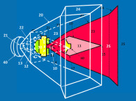
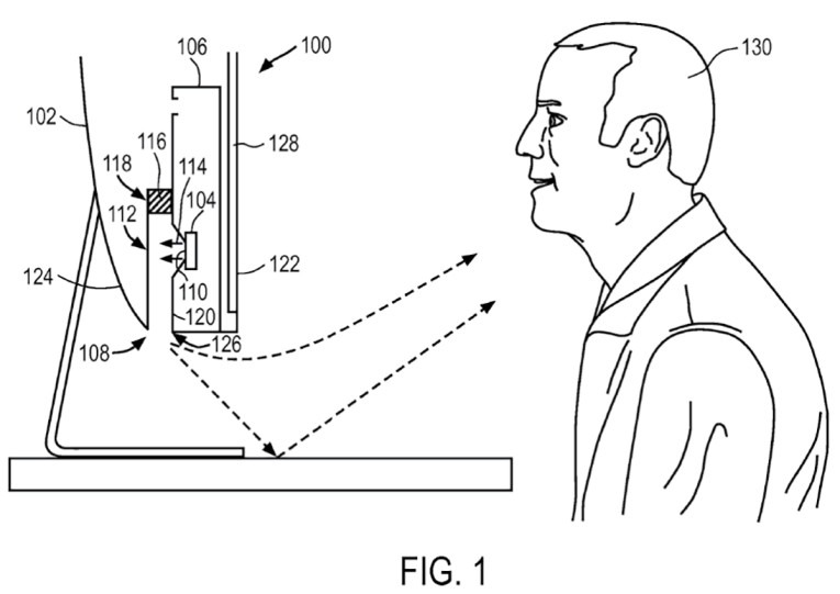
An electronic audio device including an enclosure having an acoustic output opening and a speaker positioned within the enclosure. The speaker and the acoustic output opening are acoustically coupled by an acoustic output pathway. The acoustic output pathway includes a damping chamber to dampen a resonance frequency of the acoustic output pathway. The speaker is between the damping chamber and the acoustic output opening (see Figure 1 of the Patent).
Independent Claims
1. An electronic audio device comprising: an enclosure and a base; the enclosure having a bottom wall and a front wall, wherein an acoustic output opening is formed in the bottom wall of the enclosure and the front wall of the enclosure includes a flat panel display; a speaker positioned within the enclosure, the speaker having a sound emitting surface positioned behind the flat panel display; an acoustic output duct connecting the speaker to the acoustic output opening in the bottom wall of the enclosure, the acoustic output duct including a planar face and a sidewall connected to the planar face, the acoustic output duct having a damping chamber at a position upstream from the speaker and an exit port at a position downstream from the speaker, the planar face extending from the damping chamber to the exit port; and wherein the acoustic output opening in the bottom wall of the enclosure is positioned at a distance from a bottom of the base and sound emitted from the acoustic output opening is directed toward a plane that is parallel to the bottom of the base.
9. An electronic audio device comprising: an enclosure and a base; the enclosure having a front wall, a back wall and a bottom wall, wherein a flat panel display is mounted to the front wall and an acoustic output opening is formed in the bottom wall; a speaker is positioned within a portion of the enclosure between the display and the back wall such that the speaker is spaced a distance from the acoustic output opening; an acoustic output pathway acoustically coupling the speaker to the acoustic output opening that is formed in the bottom wall; a damping chamber connected to the acoustic output pathway to dampen an acoustic response of the acoustic output pathway, the damping chamber positioned between the display and the back wall such that the speaker is positioned along the acoustic pathway between the damping chamber and the acoustic output opening in the bottom wall; the acoustic output pathway including a planar face, and a sidewall connected to the planar face, wherein the planar face extends from the damping chamber to the acoustic output opening in the bottom wall, and a length of the pathway from the damping chamber to the acoustic output opening in the bottom wall is greater than its width; and wherein the acoustic output opening in the enclosure’s bottom wall is positioned at a distance from a bottom of the base and sound emitted from the acoustic output opening is directed toward the bottom of the base.
17. An electronic audio device comprising: an enclosure and a base; the enclosure having a bottom wall and a front wall, wherein an acoustic output opening is formed in the bottom wall of the enclosure and the front wall of the enclosure includes a flat panel display; a speaker positioned within the enclosure, the speaker having a sound emitting surface behind the flat panel display; an acoustic output duct connecting the speaker to the acoustic output opening in the bottom wall of the enclosure, the acoustic output duct including a planar face and a sidewall connected to the planar face, the acoustic output duct having a damping chamber at a position upstream from the speaker and an exit port at a position downstream from the speaker, the planar face extending from the damping chamber to the exit port; and wherein the acoustic output opening in the bottom wall of the enclosure is positioned at a distance from a bottom of the base, and sound emitted by the speaker is directed out of the exit port of the duct and then out from the acoustic output opening in the bottom wall of the enclosure toward a surface on which the bottom of the base is to rest.
Reviewer Comments
There is a range of consumer electronics devices that are not dedicated or specialized audio playback devices, yet require a built-in audio output system. For instance, smartphones, portable personal computers (e.g., laptop, notebook, and tablet computers), and desktop personal computers with built-in speakers have to integrate the loudspeakers in a manner that often compromises optimal sonic results. In cases where the speakers are built into the device and are preferably hidden from view, sound wave output from the speaker must often travel a distance within the enclosure before it exits the device. The pathway through which the sound waves travel may have resonances associated with it that cause the output from the device to vary with frequency. At some frequencies, the device may have a lot of output sound power for a given input power (resonance of the pathway). At other frequencies, the system has very little sound power output for a given input power (anti-resonances of the duct). These variations result in a reduction in audio quality and can cause significant sonic coloration.
Disclosed is an electronic audio device with an enclosure having an acoustic output opening and a speaker positioned within the enclosure. The speaker may be acoustically coupled to the acoustic output opening by an acoustic output pathway. The acoustic output pathway may have any size or shape, and in some embodiments, may be a duct. The significant aspect of the invention is to deploy one or more Helmholtz damping chambers connected to the acoustic output pathway or duct at a position that is “upstream” from the speaker. The damping chamber(s) may include an acoustic material that dampens a resonance frequency of the pathway and/or absorbs sound waves generated by the speaker, and may be applied to damp the “Q” of the Helmholtz resonant damping chamber(s).
Since the damping chamber is positioned upstream from the speaker, it does not interfere with sound waves traveling “downstream” from the speaker, toward the acoustic output opening. Instead, it is claimed, that the damping chamber absorbs sound waves reflected by the acoustic output opening in an upstream direction toward the speaker.
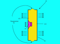
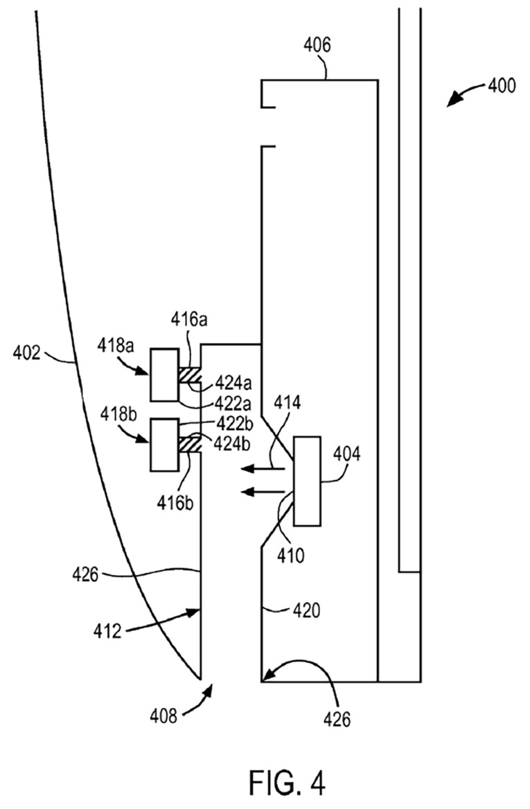
In some embodiments, the damping chamber may have a neck portion that is dimensioned to dampen a specific resonance frequency of the acoustic output pathway. In embodiments where additional damping chambers are provided, each of the damping chambers may be tuned to dampen different resonance frequencies of the acoustic output pathway and may operate with a different “Q” of the Helmholtz resonant absorption (see Figure 4 of the Patent).
This type of structure was applied to television sets in the 1980s and 1990s by Mitsubishi and Matsushita, and disclosed in numerous patents. One of the patents was US 5,604,337, “Loudspeaker Arrangement in Television Receiver Cabinet,” by Masashi Sugimoto, et al, wherein they had to mount the loudspeaker driver deep in the TV cabinet and route the sound to the front of the enclosure with a waveguide. (To Apple’s credit, it cited the Matsushita patent as prior art.) Matsushita used a similar type of damping chamber arrangement to solve the problem of damping the waveguide resonances and smoothing the resulting acoustic output at the exit of the waveguide.
With a computer optimized waveguide formation that includes Helmholtz resonant damping in the waveguide, fairly long coupling waveguides can be used to mount transducer well inside the enclosure while still producing high-quality acoustical output. If optimized to its full potential, this concept should perform well. VC
This article was originally published in Voice Coil, December 2015.