Compact Wideband Bass and Midrange Horn-Loaded Speaker System
Patent Number: 2015/0382090
Inventors: Anthony Allen Bisset (Oakland, CA)
and Quang-Viet Nguyen (Aldie, VA)
Assignee: None
Filed: June 26, 2014
Class: 381/386
Published: December 31, 2015
Number of Claims: 25
Number of Drawings: 15

Abstract from Patent
The invention is a compact high-fidelity sound reproduction system achieving high efficiency, low distortion, wide bandwidth, and extended low frequency reach and which can be used as a sub-bass woofer, bass woofer, mid-bass woofer, and mid-range speaker for residential or commercial large venue applications. The system includes a dynamic driver driven bass horn, a looped resonator duct (ring geometry), which can be folded, and an adjustable feedback duct allowing sound characteristics to be tailored.
Independent Claims
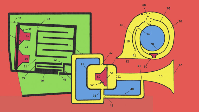
1. A sound reproduction system comprising a front horn in communication with a speaker driver, a front acoustical chamber a rear acoustical chamber, a looped acoustical duct and a feed-back duct, wherein the front chamber is in communication with a front horn, and the rear acoustical chamber is in communication with the looped acoustical duct which is in communication with the front horn by means of the feedback duct.
18. A sound reproduction system comprising one or more dynamic driver positioned between a front and back acoustical chamber with the front chamber in communication with a front horn, and a rear chamber in communication with a ring-resonator, and the ring-resonator is in communication with the front horn via a feedback duct.
19. A method of Increasing the performance of a speaker comprising the steps of harnessing the back side production of the wave compression from the diaphragm looping it around and feeding it into horn in front of the throat.
24. An acoustic trap or absorber comprising a front horn in communication with acoustic dampeners, a front acoustical chamber and a rear acoustical chamber separated by either a damped passive membrane or a dynamic driver that is electrically shorted with a resistor or mechanically-damped, a looped acoustical duct and a feed-back duct, wherein the front chamber is in communication with a front horn, and the rear acoustical chamber is in communication with the looped acoustical duct which is in communication with the front horn by means of the feedback duct.

Reviewer Comments
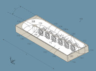
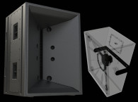
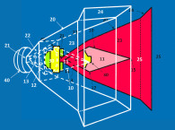
The invention as disclosed in the patent application is a loudspeaker enclosure including a front-loaded horn (i.e., an elongated waveguide having a positive flared sound passage that is in communication with the front face of a low-frequency woofer driver) with an optional front chamber, including a coupling chamber, coupling the front-facing diaphragm surface of the driver to the front horn.
Second, there is an acoustic channel that forms a loop or ring-cavity, termed a “ring resonator,” coupled to the driver’s rear face, with an optional rear chamber (an enclosure that resides on the rear facing side of the driver diaphragm) that couples the rear face of the driver diaphragm with the ring cavity, which the inventor suggests could alternately be characterized as a “traveling wave transmission line” or “unbounded resonator.”
A third component of the enclosure is a so-called “feedback-duct” that couples a point along the ring cavity to a point along the length of the front-loaded horn, creating an acoustical short around the driver. The feedback-duct is not clearly specified in the application, but is said to include the characteristic of having a volume that is approximately 15% of the volume of the ring-cavity.
The ring resonator is said to form an open circuit, (i.e., have an inlet and outlet that may or may not be in equal communication), with the back chamber, so that it can be considered a pathway with an entrance and exit that are in equal communication with the back chamber (although this symmetry may be modified to achieve certain advantages).
The purpose of the ring-cavity is said to be two-fold:
(1) It provides an acoustically long (infinite length in principle) resonator or sound propagation loop or path with the ability to sustain many harmonics by permitting waves to form in a travelling wave resonator rather than a standing wave resonator, thus, extending the bandwidth of the front horn resonator
(2) It provides these numerous travelling waves to be used in reinforcing and amplifying certain frequencies in the front horn to effect a smoother frequency spectrum of sound waves that are sustained in the front horn which follows percent-wave behavior for the most part.
It is suggested that the feedback duct, coupled between the ring cavity and the front horn, serves to control and regulate the rate and/or phase of the energy transfer between the “front horn resonator” and the ring resonator/rear chamber. (It is unclear to this reviewer what the term “rate of energy transfer” means in this case. Possibly “amplitude”.)
Additionally, it is stated that, the feedback duct is an integrated conduit that provides a path of integration between the looped acoustical duct and the horn mouth, and it serves as a means to enable energy transmission from the looped acoustical duct to the front horn that can be used to control the “rate of energy transfer” between the ring resonator and the front horn where there may be an asymmetrical bias from the initial speaker driver push.
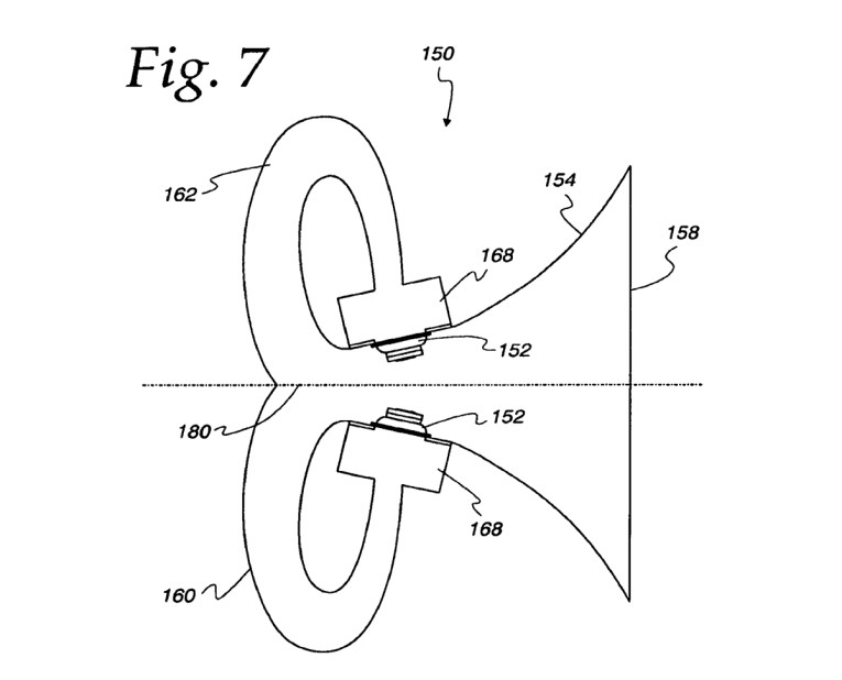
It is further disclosed that the invention comprises a wave generation or propagation device that provides a horn connected at the rear end to a ring resonator (that may further be a folded ring resonator), which is also in dynamic communication with the front of the horn by means of a feedback duct. In a further aspect of the invention, the feedback duct is adjustable, such as in width and length or volume. Changes can be made to the surface characteristics, the material characteristic, or damping material can be added in the feedback duct to tailor the sound characteristics to achieve a specific effect.
Changes in the geometry of the feedback duct changes the bass extension, wherein a wider or shorter duct allows a lower bass extension, but at the expense of reduced sound pressure level. Alternatively, a narrow or long channel results in a more gradual rate of sound fall-off in the low frequencies. For example, some may prefer the rapid falloff but deeper bass extension, and in this case, the feedback duct has a larger aspect ratio.
The aspect ratio of the feedback duct is the ratio of the width (thickness of the feedback duct channel) divided by the length and in the following ranges depending on the frequency application 0.01 to 0.1, and in categories of 0.01 to 0.03; 0.03 to 0.05; and 0.05 to 0.1, said to be corresponding to studio mastering/mixing monitoring; high fidelity/home theater; and pro audio/public address applications, respectively.
The feedback duct allows for phase sensitive feedback where the feedback of the pressure wave in the front horn is affected by means of the length of the feedback duct, which enables the phase of the front and back of the speakers drivers to combine at an optimal phase, (i.e., smaller than 90°). Finally, the system provides an interface between the ring resonator and the front horn that happens in such a way to allow the phase recombination to be optimized.
The theoretical basis and design specifications for preferred embodiments of the invention are rather limited in the disclosure. It may even be that the inventors are not sure how the system works, as there is an unusual disclaimer in the patent: “In the event that the principle and modes of operation described herein is shown at a later time to be incorrect, the uniqueness and novelty of the speaker alignment and topology is still valid.”
The basis of operation can best be understood by starting with what has come to be known as a tapped horn or tapped waveguide, as shown in William E. Glenn’s US Patent 2,765,864 and Thomas J. Danley’s US Patent 8,457,341.
The “tapped” rear wave of the woofer diaphragm in the tapped horn example is coupled back into the primary horn, near to the mouth exit. In some configurations disclosed in the Danley patent, the “tap” includes a Helmholtz coupling chamber and duct or port, with a single tuning frequency tuned to an upper range frequency of the system, to smooth the response near and/or above the 1-wavelength frequency of the horn.
In the current invention, the “feedback duct” replaces the port or duct of the Danley design, and the Helmholtz chamber is replaced with the aforementioned “ring-cavity”, which can operate as a singular or multiple (if asymmetrical) odd-quarter-wave tuning frequencies. The complexity (and potential increase in size) of this approach, properly aligned, can provide a significant advantage in the smoothing and usability of the upper frequency range, which is a fundamental limitation of tapped pipes and horns, often limiting the smooth portion of the bandwidth to as little as two octaves. The primary advantage of the tapped driver back-wave is to create a more effective summation at the half-wavelength frequency of the waveguide, increasing output and minimizing a broad dip in the response that can develop at that frequency.
The approach to smoothing the response of tapped systems, as disclosed in this patent application was developed in a prototype by the late David Graebener a little more than 5 years ago. His studies uncovered that most versions of this type of architecture were larger than a tapped waveguide for a given efficiency and low frequency cut-off frequency.
But, it was found to be an effective tool to optimize the phase and amplitudes of the extended tap, or “feedback duct,” in the parlance of the patent application under review, to eliminate out-of-phase cancellations and resonant peaks, allowing an extension of the upper passband limit by two or more octaves. Other details were explored that allowed some simplification of the system, particularly relating to the reconfiguration of the ring-cavity.
It is commendable that the inventors included modeled and actual measured frequency response curves in the patent application, which are illustrative of the system’s smoother response capability as compared to the prior art tapped waveguides.
Assuming that the curves are accurate, the inventors have achieved a good balance between maintaining output at the half-wavelength frequency (approximately two-times FC) while effectively taming the roughness at and above the one-wavelength frequency.
The main question is whether you can accomplish this capability without substantially increasing the system’s total enclosure volume significantly above that of prior art devices of similar performance. That being the case, the approach should provide high output systems with greater useful bandwidth than prior art tapped waveguides. VC
This article was originally published in Voice Coil, April 2016.