Title: Linear Motor Magnet Assembly and Loudspeaker Unit
Patent Publication Number: 2022/0191621 - US Patent: US20220191621A1
Inventors: Timothy Ruben Scheek (Amsterdam, NL)
Assignee: Mayht Holding B.V.
Filed: July 18, 2019
Current International Classes: H04R 9/06 20060101 H04R009/06
Granted/Published: June 16, 2022
Number of Claims: 17
Number of Drawings: 5
Abstract from Patent
A linear motor magnet assembly 2 for use in a loudspeaker unit 1, with a fixed base actuator component 4 and a membrane actuating element 5, the membrane actuating element 5 having a linear excursion axis A. A first auxiliary magnetic element 7 and a second auxiliary magnetic element 8 are present, the first auxiliary magnetic element 7 providing a first auxiliary spatial magnetic field with a major axis aligned with the linear excursion axis A. The second auxiliary magnetic element 8 is fixedly connected to the membrane actuating element 5 of the linear motor magnet assembly 2 and has a second auxiliary spatial magnetic field, the second auxiliary magnetic field overlapping the first auxiliary spatial magnetic field and being substantially similarly oriented as the first auxiliary spatial magnetic field over a first predetermined excursion range E1 of the linear motor magnet assembly 2.
Independent Claims
1. A linear motor magnet assembly for use in a loudspeaker unit, the linear motor magnet assembly comprising a fixed base actuator component and a membrane actuating element, the membrane actuating element having a linear excursion axis (A), the linear motor magnet assembly further comprising a first auxiliary magnetic element (7) and a second auxiliary magnetic element, the first auxiliary magnetic element providing a first auxiliary spatial magnetic field with a major axis aligned with the linear excursion axis (A) of the linear motor magnet assembly, the second auxiliary magnetic element being fixedly connected to the membrane actuating element of the linear motor magnet assembly and having a second auxiliary spatial magnetic field, the second auxiliary magnetic field overlapping the first auxiliary spatial magnetic field and being substantially similarly oriented as the first auxiliary spatial magnetic field over a first predetermined excursion range (E1) of the linear motor magnet assembly.
Reviewer Comments
Last month, we reviewed one of the early Mayht patents covering their general bipolar, interleaved multiple motor structure architecture that is the basis for a number of their stated claims in terms of performance and packaging.
This month’s entry is a continuation of the series of reviews on the new Mayht transducer technology recently acquired by Sonos for the tidy sum of $100 million dollars. We will delve into their most recent US publication (June 16, 2022), which addresses the most dramatic claim of all “Air pressure issue solved,” with the ability for the transducer technology to allow a contravention of Hofmann’s Iron Law and provide a greater-than 10× reduction in enclosure volume, while maintaining the same efficiency and bandwidth as compared to the current state of the art.
If this aspect of their technology were found to be valid and it could achieve this level of miniaturization without a significant cost or performance penalty, one could argue, that no other loudspeaker company would be able to compete with this >10-to-1 scale of advancement.
As previously mentioned, the Mayht topology in general appears to be a useful innovation relative to efficient packaging, such that it may allow a slightly smaller device for a given performance. But to achieve anything that could provide at least a 3-to-1 size advantage, and certainly if it can achieve a 10-to-1 size reduction, a sophisticated technological advancement would have to be applied. Historically, the substitution of the internal atmosphere with specialized gasses, heated, Freon-filled absorption fibers, and advanced materials, has tended to be limited to enclosure expanding conferrals of less than 3-to-1, and most of those have included undesirable side effects, such as high levels of damping, which ultimately undermined any potential gains.
To achieve something anywhere near to a 10-to-1 reduction in enclosure volume has only been approached theoretically, or realized in the lab, in a manner that was not practical as a real-world device. The two methods that have at least suggested a possibility of overturning Hofmann’s Iron law, (where it is known that to have an improvement in any one of efficiency, bass bandwidth, or enclosure volume requires a commensurate compromise in one or both of the remaining parameters) have been that of a stabilized vacuum enclosure, or a negative spring applied to the woofer diaphragm, to offset the stiffness of the enclosure air spring. The first of the two solutions, the vacuum enclosure with a positive spring counterbalancing force, while exhibiting the greatest theoretical potential, is fraught with a variety of practical problems, from maintaining a vacuum seal to dealing with crushing forces on the diaphragm and suspension components, and, much more.
The Negative Spring systems, as we have discussed in previous reviews, operate based on having an additional apparatus built into a transducer, which applies a force that is in opposition to the air spring of the enclosure.
A simple example form of a mechanical negative spring is an old-fashioned light switch, or toggle-switch, where it is very difficult to hold it in the center position; as it has a tendency to pop in one direction or the other. This same concept is applied to the moving system of a woofer, wherein when it moves into the enclosure, the “negative spring” pushes the diaphragm into the enclosure, ideally with an opposite and complementary force to the stiffness of the air volume of the enclosure, overcoming that air spring stiffness. Same thing happens when the woofer cone moves outward, wherein the negative spring would help overcome the increasing vacuum applied to the diaphragm. If one could make this bi-directional, negative spring have just the right spring force and also the ability to remain stable and steady in its center position, they would potentially have a working system that, from the standpoint of the low-frequency driver, could make the enclosure seem larger than it really is.
Some negative spring experiments have at least shown some promise in the lab, and there have been hundreds of attempts to create practical devices since the first efforts in the mid-1950s, but to-date these have continued to elude some of the most brilliant minds in the business, with nary a single product based on this technique ever making it to market.
With the negative spring based systems, the “anti-spring” portion can be realized with three different techniques: a mechanical negative spring, as with the light switch analogy; a pneumatic negative spring (e.g., two balloons being pushed together and tending to move in one direction or another); and a magnetic negative spring, arranged to use either a multiple magnet repelling force, or attracting force, to assist pushing or pulling the woofer diaphragm into, or out of, the enclosure.
The invention disclosed in the current Mayht patent application publication is a means to reduce enclosure volume while maintaining efficiency and bass bandwidth by applying an additional “auxiliary” magnetic system to enhance the transducer’s ability to overcome enclosure air spring stiffness by using this magnetic system as a compliance augmentation device. (Going forward, any references to "auxiliary magnetic elements 7 and 8" identifies the additional magnetic components added to form the “negative magnetic spring”.)
As stated by the inventor: “The present invention provides in various embodiments a device using a combination of at least two permanent magnets to improve the performance of a linear motor actuator system by effectively decreasing the enclosure and suspension stiffness over the complete excursion range of the linear motor, effectively decreasing the power needed by the linear motor system to travel over the excursion range. The present invention provides in various embodiments a device using a combination of at least two permanent magnets to improve the performance of a linear motor actuator system by decreasing the stiffness over the complete excursion range of the linear motor, effectively decreasing the power needed by the linear motor system to travel over the excursion range.”
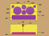
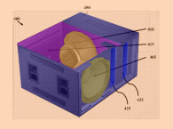
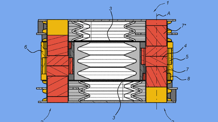
Figure 1a shows a cross sectional view. Figure 1b shows a perspective view of one embodiment of the present invention loudspeaker unit 1 having two opposing membranes 3, each being driven by two linear motor magnet assemblies 2, on opposite corners of the transducer where the additional compliance enhancing magnet structures have also been implemented.
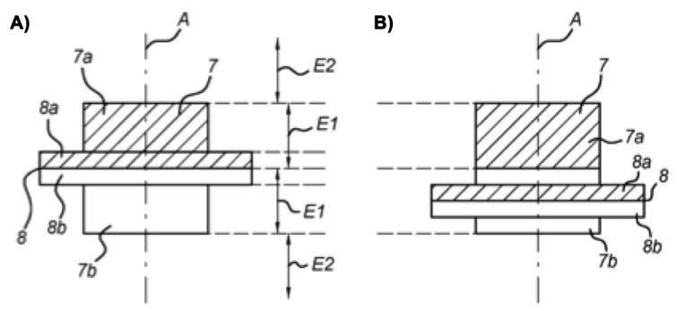
Figure 1b: This image illustrates a perspective view of the invention with two opposing membranes, each being driven by two linear motors and additional compliance increasing magnet assemblies.
The magnet assembly 2 comprises a fixed base actuator component 4 and a membrane-actuating element 5 (such as a voice coil or a mobile magnet in a moving magnet based motor). The fixed base actuator component 4 is mechanically connecting two axially aligned magnetic elements 7 and 7* which are part of the linear motor magnet assembly 2. The material of the fixed base actuator component 4 is of a non-magnetic material, ensuring a proper magnetic field distribution for cooperation between the two axially aligned magnetic elements 7, 7* and a membrane actuating element 5.
The membrane-actuating element 5 is moveable and has a linear excursion axis A, (i.e., the direction in which the membrane 3 moves up and down). Upon actuation, the membrane-actuating element 5 moves the magnetic assembly 2 that is connected to the membrane 3. The motor magnet assembly 2 further comprises a first auxiliary magnetic element 7 (one of the two axially aligned magnetic elements 7, 7*) and a second auxiliary magnetic element 8. The first auxiliary magnetic element 7 provides a first auxiliary spatial magnetic field with a major axis aligned with the linear excursion axis A of the motor magnet assembly 2. The second auxiliary magnetic element 8 is fixedly connected to the membrane actuating element 5 of the linear motor magnet assembly 2 and has a second auxiliary spatial magnetic field. The second auxiliary magnetic field overlaps the first auxiliary spatial magnetic field and is substantially similarly oriented as the first auxiliary spatial magnetic field over a first predetermined excursion range E1 of the linear motor magnet assembly 2.
Loudspeaker unit 1 has two opposing membranes 3 that are placed on the upper and the lower surfaces of the loudspeaker unit 1. The base element of each of the membranes 3 is structurally connected to two linear motor magnetic assemblies 2 at two of the diagonal ends of the membrane 3. As shown in Figure 1b, the base element of the lower membrane 3 is structurally connected by two different linear motor magnetic assemblies 2 that are positioned on both of the membrane’s lower diagonal ends and the base element of the upper membrane 3 is structurally connected by two different linear motor magnetic assemblies 2 that are positioned on both of the membrane’s upper diagonal ends. The effect of this combination of features is an increasing magnetic force (or a reduced stiffness) in the excursion direction in the first predetermined excursion range (i.e., the first and second auxiliary magnetic element are aiding in overcoming the suspension force and air compression forces in the loudspeaker unit 1). The second auxiliary magnetic element 8 is attached to the membrane actuating element.
In an additional embodiment, the second auxiliary magnetic element 8 is positioned at a first distance along the linear excursion axis A from the membrane-actuating element 5. Figure 2a shows an operational situation in which the second auxiliary magnetic element 8 is positioned at the center of the first auxiliary magnetic element 7 along the linear excursion axis A. Figure 2b shows an operational situation in which the second auxiliary magnetic element 8 is positioned away from the center of the first auxiliary magnetic element 7 along the linear excursion axis A, representing a movement of the actuating element, or voice coil, making an excursion for which the auxiliary magnetic elements augment the movement of the voice coil with an additional force, used to offset at least a portion of the enclosure and suspension stiffness.
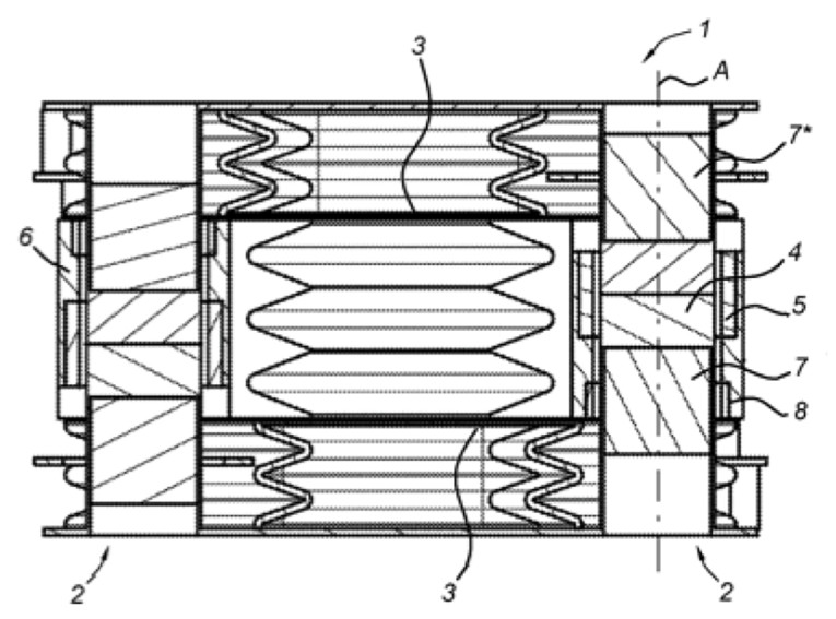
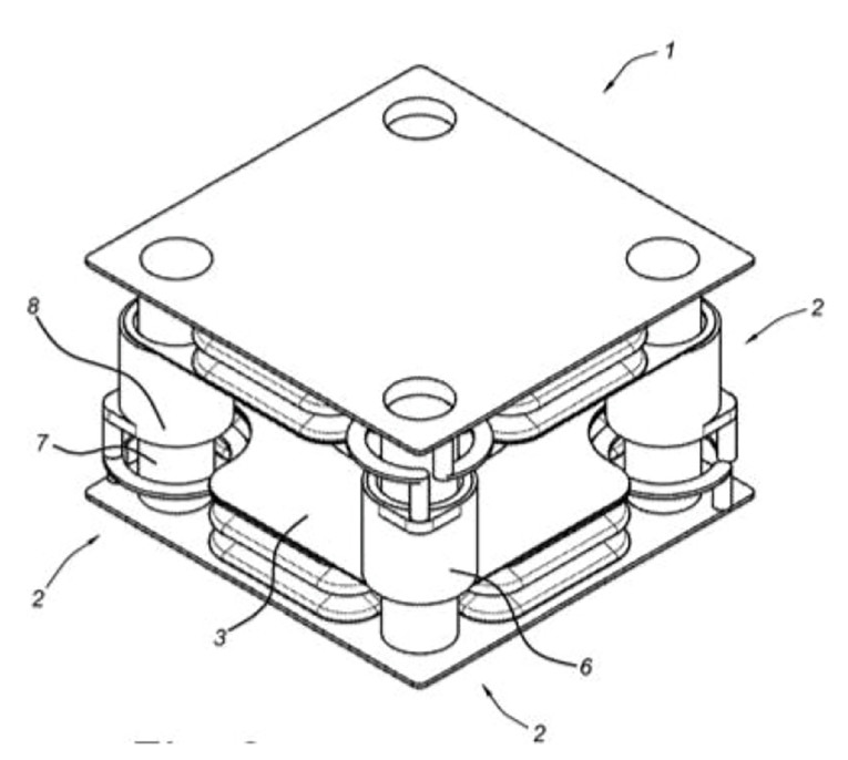
Figure 2: Figure 2a and Figure 2b show an example of the repulsion version of the permanent magnet compliance enhancing structure in two operational situations.
Another form of the invention relates to the linear motor magnet assembly, wherein the first auxiliary magnetic element 7 has a predetermined shape, providing a predetermined first auxiliary spatial magnetic field profile over the excursion range of the linear motor magnet assembly. The predetermined shape can be a double (e.g., truncated) cone shape with a largest diameter at a middle part of the first auxiliary magnetic element 7. This can be implemented by having one of the magnets as a cone shaped magnet, wherein that shape creates a magnetic field of varying strength over the excursion. This is said to allow the system to more efficiently control the relative movement of the second auxiliary magnetic element 8 with respect to the first auxiliary magnetic element 7 considering the varying strength of the magnetic field.
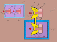
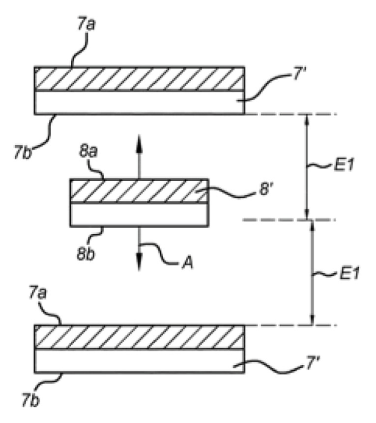
Figure 3 shows a cross-sectional view of a linear motor magnet assembly in accordance with a further variation of the present invention, comprising two magnetic bodies 7’ opposed to each other forming the first auxiliary magnetic element, with a magnetic body 8’ forming the second auxiliary magnetic element positioned in between such that a permanent magnet 8’ is mounted on the membrane of the loudspeaker unit, and static magnets 7’ are placed above and beneath the membrane. As opposed to the previous embodiments, where the repulsion of two magnets with like polarities, the Figure 3 embodiment represents a center magnet with an opposite polarity relative to the outer magnets, such that the center magnet, connected to the diaphragm, is attracted to the lower magnet on an inward diaphragm movement caused by the voice coil and the primary motor system and attracted to the upper magnet during and opposite, an outward diaphragm movement caused by the voice coil and the primary motor system.
The last seven paragraphs represent essentially the full teaching of the patent. Any additional text appears generally repetitive and doesn’t appear to teach any substantial novelty or basis for how to fully optimize such a negative magnetic spring system. If it has any unique aspects, it would seem they are focused on how prior art magnetic negative spring concepts can be adapted to the Mayht transducer architecture.
For example, Figure 4 is one of the earliest prior art magnetic negative spring woofer systems from a German patent filed in 1967, DE1,299,327B, “Lautsprecher mit Kolben insbesondere Konusmembrane” (Loudspeaker with Particular Cone Piston Diaphragm) by Edmund Meyer, assigned to Isophon Wereke.
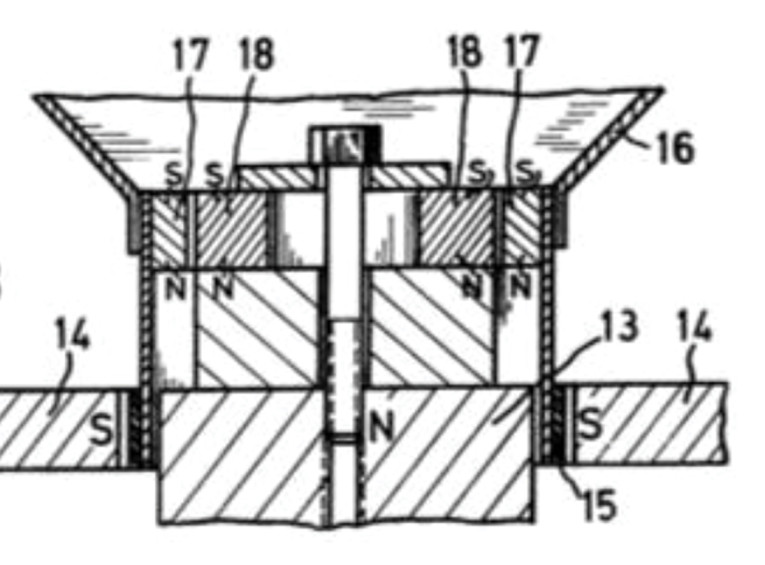
It can be seen in Figure 4 that the conventional portion of the motor includes the voice coil 15 located in the magnetic gap between magnet 13 and the magnetic return top plate 14. The additional, auxiliary, ring magnets 17 (mobile and attached to the neck of the diaphragm 16) and 18 (fixed and attached to the center pole piece) are coaxially aligned, and magnetized with the common polarities adjacent each other when the diaphragm is in the resting position. It can be seen that magnet 17 would be unstable and have a tendency to move in repulsion from stationary magnet 18, applying a force to the diaphragm 16, compelling it to move up or down. Ideally, when mounted in an enclosure, as the program signal would cause the voice coil 15 to urge the diaphragm into the enclosure, compressing the enclosed air spring, the mobile auxiliary magnet 17 would add an additional force, “assisting” the movement of the diaphragm against the air spring and into the enclosure. The opposite action would happen upon the program signal moving the diaphragm out of the enclosure with the auxiliary magnet 17 adding force to offset the air spring (and suspension) from keeping the diaphragm from moving out of the enclosure.
While at first this seems like an excellent expedient toward overcoming the air spring stiffness of the enclosure, there are many troublesome issues that must be overcome to make the system practical. The first, and foremost, is that of the instability of the auxiliary magnets and their tendency to move off-center relative to the constant magnetic forces, independent of the program signal. In any of these systems, if the auxiliary magnetic forces are so powerful as to be adequate to the task of overcoming the air spring stiffness of a small enclosure, then they will also have a greater tendency for instability. Therefore, any negative spring based transducer, must also have an additional device of some type that can compensate for the instability.
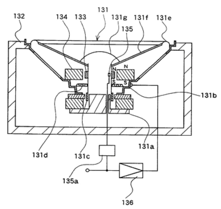
Figure 5 is a prior art magnetic negative spring woofer from a 2003 patent, US6,574,346, “Bass Reproduction Speaker Apparatus” by Shoji Tanaka, assigned to Matsushita Electric. Its auxiliary magnetic circuit is very similar to that of the German patent in Figure 4, with mobile magnet 133 attached to the voice coil former and repelling from the common polarity of the fixed magnet 134, but in this device a Hall element senses any offset with feedback to a power amplifier in order to correct for any unstable mobility unrelated to the program input signal. This approach and other separate systems, such as slow reacting air pumps raising or lowering the pressure at a less than 5Hz rate, have been applied in an attempt to correct for any drift in diaphragm position. Such a system and negative spring devices in general, are explored in a paper in the Journal of the Acoustical Society of America in 1971, written by Terrance Matzuk from Gulf Research, and titled: “Improvement of Low-Frequency Response in Small Loudspeaker Systems by Means of the Stabilized Negative-Spring Principle.”
A second issue with negative spring devices is that of getting the “spring rate,” or change in stiffness relative to change in diaphragm position, of the magnetic counter-force, to match that of the suspension and air spring in the enclosure over an adequate range of excursion. With the repulsion type magnetic negative springs, the magnet force tends to be very strong as it first moves off-center, but gets weaker with extended excursions, as the centers of magnetic force move farther apart from each other. For short excursions the spring rates can be matched more easily, but for any significant diaphragm excursions, which will tend to be greater in these smaller, “negative spring, miniaturized” devices, for a given output the issue becomes more problematic usually requiring larger auxiliary magnetic structures in an attempt to at least minimize the problem.
This is where some explorers of this concept have abandoned the “repulsion” approach and have used additional magnets to an attempt to utilize magnetic “attraction” instead.
A third issue is that the addition of the auxiliary magnet being attached to the voice coil bobbin or neck of the diaphragm, can substantially increase the moving mass of the transducer, which can reduce efficiency in a system that has the goal of maintaining efficiency, while extending low frequencies.
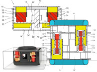
The prior art device in Figure 6 shows a magnetic negative spring woofer from a patent filed in 2005, US7,724,915, “Speaker Device” by Toshiyuki Matsumura, and Shuji Saiki, assigned to Panasonic Corp. This system offers an alternative approach in an attempt to address the second and third issues.
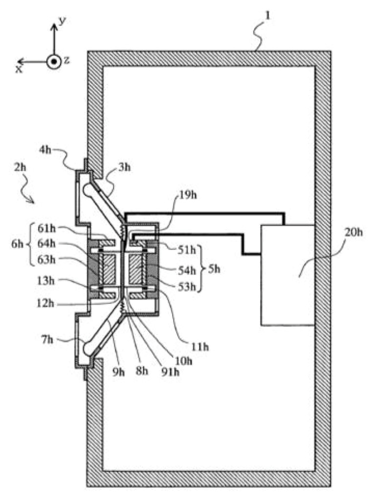
It can be seen in Figure 6 that stationary magnets 64h and 54h are above and below the diaphragm 9h, which has a center portion 91h of the diaphragm, which is made of magnetic material other than a magnet, such that as the diaphragm is driven by voice coils 11h and 13h, the magnetic material of the diaphragm is “pulled” with additional force in the same direction to help offset the air spring stiffness of the enclosure. In this case, the force of the auxiliary magnets on the diaphragm increases as the diaphragm gets closer to magnet 64h or 54h, which can complement the air spring stiffness increasing as the diaphragm moves further in either direction.
A magnet could be used in place of the magnetic material 91h, but in this embodiment of the prior art patent, 91h uses a magnetic material other than a magnet to reduce the moving mass impact of a magnet.
Of course, any magnetic material, such as iron or permalloy sheet will have greater mass than standard diaphragm materials, but potentially much less than the magnet. This prior art patent also teaches the use of a variety of different types of sensing and feedback stabilization systems to help maintain the behavior of the fundamental instability of the negative spring system. With each of these additional variations of this system type, there have historically been pitfalls that have not been overcome, at least not in a practical manner that resulted in a net advantage over a conventional system.
Many years ago, a very talented engineer and owner of a prominent subwoofer company, shared his stories of the long and painful attempt to realize a practical negative spring woofer system. By the time he increased the negative spring rate to adequately overcome the air spring of the enclosure and provide significant reductions in enclosure volume, the feedback correction power required to maintain stability and keep the woofer from getting “stuck” all the way at one excursion extreme or another, required more amplifier power than was required to merely equalize a conventional, optimized driver in the same, small-sized enclosure. I’m certain that this effort has been duplicated many times at various loudspeaker companies over the years.
This brings us back to Mayht and their magnetic negative spring patent and the reference to their claim of greater than a 10x reduction in enclosure volume. While the patent puts forth a good starting point for developing a compliance enhancement system, as many patents have done in the past, it certainly doesn’t teach how to reduce this type of system to practice in a manner that addresses the various additional issues that cannot be ignored if one is to have a successful outcome.
There are no specification of any of the forces and magnetic and air stiffness relationships, no measurements or specificity in claimed outcomes, and no mention of any supplemental electronics that may be required to control and stabilize the system.
The Mayht patent claims “to provide a more energy efficient linear movement system" and "the permanent magnets being placed in a way that the combined magnetic fields of the permanent magnets of the permanent magnet system counter the increasing stiffness over the excursion of the linear motor actuator system.” It uses both the repulsion magnetic layout and a magnetic attraction approach where a permanent magnet is on the membrane of the loudspeaker unit, and static magnets are placed above and beneath the membrane.
The basic architecture is in place to achieve some level of a compliance enhancement effect, but it is difficult to determine the effectiveness of the system as disclosed. Additionally, in this reviewer’s interpretation, it would appear that the primary independent patent claim substantially describes the prior art, so it may be difficult to get the US Patent and Trademark Office (USPTO) to grant their application as it stands currently.
Overall, it is still an exciting proposition, and again, one would have to assume that Sonos applied significant diligence and achieved substantial verification before writing the check. But, one can only presume that a greater than 10× reduction in enclosure volume would require significant additional magnetic counter force, which would cause even greater instabilities, such that if this is a practical system as claimed, we will be learning much more about how the device is optimized and most likely will be reviewing another much more in-depth patent describing those details. VC
This article was originally published in Voice Coil, August 2022