Controlled Passive Radiator
Patent Number: US20180103313A1
Inventor(s): Tony Doy (Santa Barbara, CA)
Assignee: Sonos, Inc., Santa Barbara, CA
Filed: October 6, 2016
Published: April 12, 2018
Number of Claims: 21
Number of Drawings: 9
Abstract from Patent
Example techniques may involve controlling a passive radiator. An implementation may include a device buffering successive samples of audio content. For sets of buffered samples, the device predicts excursion of the passive radiator caused by playback of the respective set of buffered samples by active speakers via a model. The device limits excursion of the passive radiator to less than an excursion limit when certain sets of buffered samples are predicted to cause the passive radiator to move beyond the excursion limit. The device plays back the successive samples of the modified audio content via the active speakers. The device measures excursion of the passive radiator when sets of buffered samples are played back via the active speakers. For sets of samples, the device determines respective differences between the predicted excursion and the measured excursion and adjusts the model to offset determined differences between the predicted and measured excursion.
Independent Claims
1. A playback device comprising: one or more active speakers; a passive radiator; one or more processors; and computer-readable media having stored therein instructions executable by the one or more processors to cause the playback device to perform operations comprising: buffering successive samples of audio content; for sets of one or more buffered samples, predicting, via a forward prediction model, excursion of the passive radiator caused by playback of the respective set of buffered samples by the one or more active speakers; limiting excursion of the passive radiator to less than an excursion limit when certain sets of buffered samples are predicted to cause the passive radiator to move beyond the excursion limit, wherein limiting excursion of the passive radiator comprises modifying the audio content to lower sound pressure levels of the buffered samples that are predicted to cause the passive radiator to move beyond the excursion limit; playing back the successive samples of the modified audio content via the one or more active speakers; measuring excursion of the passive radiator when sets of buffered samples are played back via the one or more active speakers; for sets of one or more samples, determining respective differences between the predicted excursion and the measured excursion; and adjusting the forward prediction model to offset determined differences between the predicted excursion and the measured excursion.
8. A tangible, non-transitory computer-readable medium having stored therein instructions executable by one or more processors to cause a playback device to perform a method comprising: buffering successive samples of audio content; for sets of one or more buffered samples, predicting, via a forward prediction model, excursion of a passive radiator caused by playback of the respective set of buffered samples by one or more active speakers; limiting excursion of the passive radiator to less than an excursion limit when certain sets of buffered samples are predicted to cause the passive radiator to move beyond the excursion limit, wherein limiting excursion of the passive radiator comprises modifying the audio content to lower sound pressure levels of the buffered samples that are predicted to cause the passive radiator to move beyond the excursion limit; playing back the successive samples of the modified audio content via the one or more active speakers; measuring excursion of the passive radiator when sets of buffered samples are played back via the one or more active speakers; for sets of one or more samples, determining respective differences between the predicted excursion and the measured excursion; and adjusting the forward prediction model to offset determined differences between the predicted excursion and the measured excursion.
15. A method comprising: a playback device buffering successive samples of audio content; for sets of one or more buffered samples, the playback device predicting, via a forward prediction model, excursion of a passive radiator caused by playback of the respective set of buffered samples by one or more active speakers; the playback device limiting excursion of the passive radiator to less than an excursion limit when certain sets of buffered samples are predicted to cause the passive radiator to move beyond the excursion limit, wherein limiting excursion of the passive radiator comprises modifying the audio content to lower sound pressure levels of the buffered samples that are predicted to cause the passive radiator to move beyond the excursion limit; the playback device playing back the successive samples of the modified audio content via the one or more active speakers; the playback device measuring excursion of the passive radiator when sets of buffered samples are played back via the one or more active speakers; for sets of one or more samples, the playback device determining respective differences between the predicted excursion and the measured excursion; and the playback device adjusting the forward prediction model to offset determined differences between the predicted excursion and the measured excursion.
Reviewer Comments
Active, powered loudspeakers have a variety of advantages over fully passive implementations. In fact, I would suggest that one day engineers will look back and think it was pretty silly that we worked so hard to get these primitive passive loudspeakers to behave instead of making all loudspeakers active.
In the realization of an active loudspeaker, one of the many useful techniques that has been applied is that of “motional feedback” (MFB)—the sensing of the motional output of the transducer diaphragm to monitor the device’s behavior as compared to the reference input signal and realize a difference signal to be used to determine an appropriate compensation for any correctable errors.
While the approach can be applied to compensate for many small and large signals, linear and nonlinear effects, the greatest subjective impact is often derived from the ability to correct for large signal nonlinearities that occur at the overload limits of the transducer.
The technical literature is rich with investigations into applying MFB to loudspeakers, with one of the seminal reference papers being that of Egbert De Boar, “Theory of Motional Feedback,” IRE Transactions on Audio, January–February, 1961. One of the earliest documents describing an actual reduction to practice of a practical MFB loudspeaker was “A Motional Feedback loudspeaker System” written up in the Philips Technical Review (Volume 29, No. 5, 1968) by J. A. Klaassen and S. H. de Koning of Philips Electronics.
Philips is widely credited with introducing the first loudspeaker product incorporating MFB in 1973 (the RH532, known affectionately as David for its small size and powerful sound). But, it was actually Panasonic (Matsushita), applying Luxman’s SQ-65 MFB, vacuum tube, motional feedback electronics in loudspeaker systems in the early 1960s — models: 12P-X3 tri-axial and EAB-8M2 Speaker Systems — that appear to be the first commercial product to incorporate MFB. Those of you who enjoy such things will be entertained by the thorough operating manual, including schematics, operational principles, and factory assembly line pictures, which can be found here.
Try finding an owner’s manual like that with any product made currently. Audio hobbyists were seriously involved with all technical aspects of their equipment in those days.
Of course, as with so many audio technologies, the first inventor did not see his creative ideas realized in production and that also seems to be the case with MFB loudspeakers—for which the earliest patent appears to be US Patent 2,194,175, “Distortion Reducing Arrangement” to Karl Wilhelm, filed just one year after the two famous 1937 patents on negative feedback in power amplifiers, by H. S. Black and H. T. Nyquist were granted.
Even though there are dozens of patents and papers on MFB loudspeakers, the vast majority address only sealed, acoustic suspension-type loudspeakers. Even with such a simple device as a closed-box loudspeaker, with a singular resonant frequency, there are already difficulties in dealing with the behavior of a feedback-based corrective system.
One of the primary issues is that the phase shift of the system at, and near, the fundamental resonant frequency can convert a (acceleration-based) feedback system into a feed-forward system and measures have to be put in place to address this condition. It is beyond the scope of this review to provide a complete discussion of this issue, but for those interested, it is covered in almost every paper on feedback and explored in a particularly clear and concise manner on pages 103 to 106 of the third edition of John Borwick’s comprehensive reference, Loudspeaker and Headphone Handbook.
When it comes to incorporating MFB into a bass-reflex system, the complexity of the variables to be addressed due to delay/phase effects is increased. Among the dearth of papers written on the application of MFB to bass reflex systems, two appear to provide a good representation of both the difficulties and what is possible when applying MFB to vented enclosures, those papers are: “Current Controlled Vented Box Loudspeaker System with Motional Feedback” by Philippe Robineau and Mario Rossi, from the 108th Audio Engineering Society (AES) Convention, February 2000; and “On the Use of Motion Feedback as Used in 4th Order Systems” by Stephan Willems and Guido D’Hoogh, from the 126th AES Convention, May 2009. The first paper uses current drive and limits the frequency range of its MFB capability so as to be operating similarly to using MFB over the same range as with a sealed system.
The second paper, which used a very high excursion passive diaphragm radiator as the acoustic mass in the reflex system, is more comprehensive in applying an adaptive system with phase rotation and by matching complex weighting functions of three sources of feedback: 1) active driver acceleration; 2) passive radiator acceleration; and 3) current through the voice coil, making it possible to obtain effective feedback correction while maintaining the same frequency response as the passive system. Any desired equalization was performed outside of the MFB loop.
Other than delivering unintended acoustic output at lower midrange frequencies, due to internal enclosure and/or pipe resonances, a passive acoustic mass radiator in a bass reflex system tends to operate over a very narrow bandwidth that is associated with the Helmholtz resonant tuning frequency of the enclosure system, based on the acoustic mass of the passive device interacting with the air spring compliance of the enclosure volume.
When applying a feedback sensor to a passive diaphragm radiator, the radiator is pneumatically driven substantially evenly across its surface, such that it is not subject to diaphragm breakup modes that an active driver is, due to the active driver being driven at the center of its diaphragm with a voice coil. For passive radiators, this is advantageous from the standpoint of monitoring diaphragm motion, as a sensor placed most anywhere on the diaphragm will represent the displacement of all points across the diaphragm surface. Whereas, when using MFB on an active transducer, when monitoring the voice coil’s movements for feedback information about the diaphragm displacements, movements at the voice coil and neck of the diaphragm are not necessarily representations of what the diaphragm is doing at its outer regions, where breakup modes will ensue, particularly at higher frequencies of its operating range.
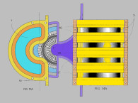
The patent under review is a bass reflex system with a passive radiator that utilizes a feedback sensor on the passive radiator. Excursions of the passive radiator, while frequency dependent, are approximately linearly related to excursion of the active speaker in the shared enclosure. Passive radiators are arranged to have maximum excursion at its resonant tuning frequency, while the active driver has an excursion minimum at the same frequency, so as to substantially increase the linear acoustic output capability of the active driver at the tuning frequency. With the active transducer moving in proportion to the voltage applied to the voice coil, in a frequency dependent manner, the excursion of a passive radiator in the enclosure is (within its mechanical limits) linearly related to the voltage applied to active transducer in the enclosure.
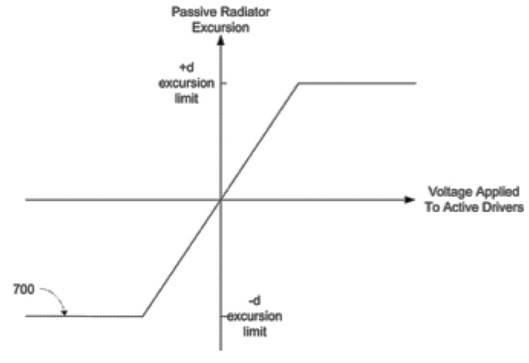
However, the relationship between the voltage applied to the active driver and excursion of the passive driver is only linear up to the positive and negative excursion limits of the passive diaphragm. These physical limits are imposed by the limits of the elastic linearity of the passive radiator’s suspension system.
At a given frequency where the output from the passive radiator is the system’s dominant acoustic output source, applying a voltage to the active driver that exceeds the positive and/or negative excursion limits of the passive radiator causes mechanical “clipping,” resulting in highly audible distortion and limiting of acoustic output.
The patent discloses techniques involved in controlling the displacement of the passive diaphragm radiator. The control involves predicting, via a forward prediction model, the passive radiator’s excursion caused by playback of audio content from the active driver.
The forward prediction model is based on the linear relationship between the voltage applied to the active driver and excursion of the passive driver. When certain portions of the audio content are predicted to cause nonlinear excursion of the passive radiator, the audio input level is modified to control the passive radiator to an excursion maximum that is at or below a predetermined excursion limit. In particular, the levels of those portions of the audio content that are predicted to cause audible overload of the passive radiator are reduced.
It is stated that, alternatively, other techniques such as modifying the phase of the input signal may also be used to cause less voltage to be applied to the active driver to limit passive radiator excursion, but it doesn’t state what phase is altered in relation to what signal, or how this would be advantageous over directly reducing the amplitude.
It is also suggested that feedback may further improve control of the radiator. When the active speaker plays back the audio content (with portions modified to limit excursion of the passive radiator), a sensor measures excursion of the passive radiator. Predicted excursion, from a forward prediction model, is compared against measured excursion for various portions of the audio content. Differences between the predicted excursion and the measured excursion can be provided as corrective feedback to the forward prediction model parameters. This feedback may cause adjustments to the forward prediction model, which may help to minimize error in the model.
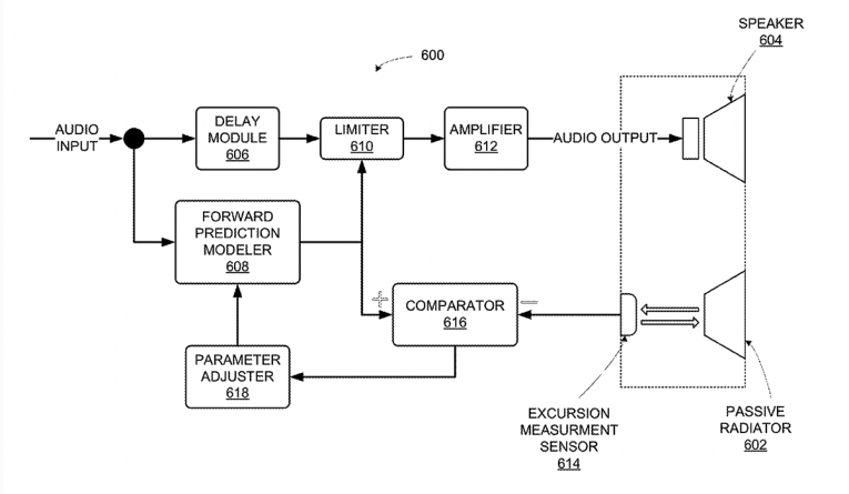
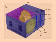
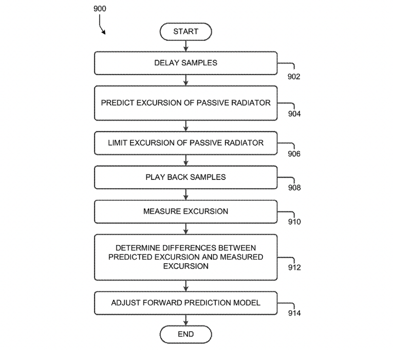
Two representative implementations are described. The first implementation includes a playback device buffering successive samples of audio content, and, for sets of one or more buffered samples, predicting, via a forward prediction model, the excursion of the passive radiator caused by playback of the respective set of buffered samples (see Figure 1 and Figure 2). Then, the system limits the excursion of the passive radiator to less than a predetermined excursion limit when certain sets of buffered samples are predicted to cause the passive radiator to move beyond the excursion limit. The system then plays back the successive samples of the modified audio content through the active speaker and measures excursion of the passive radiator. For sets of one or more samples, the system determines the respective differences, between the predicted excursion and the measured excursion and then the forward prediction model is adjusted to offset determined differences between the predicted excursion and the measured excursion.
A second implementation includes buffer-to-buffer successive samples of audio content, along with a forward prediction model to predict, for sets of one or more buffered samples, the excursion of the passive radiator. A limiter is included, to limit excursion of the passive radiator to less than a predetermined excursion limit, when certain sets of buffered samples are predicted to cause the passive radiator to move beyond the excursion limit.
An audio stage is included to play back the successive samples of the modified audio content through the active speakers and a sensor is employed to measure excursion of the passive radiator when sets of buffered samples are played. A processor is used to determine respective differences between the predicted excursion and the measured excursion and adjust the forward prediction model to offset determined differences between the predicted excursion and the measured excursion. The delays and buffering time periods are disclosed only in general terms without specific psycho-acoustical effects explored or used to quantify timing criteria.
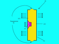
Usually, some form of quick attack and slow release is used for these types of “overload avoidance” systems, but these issues are not explored, except to suggest that limiters or compressors could be used, suggesting that the invention may comprise either real-time limiting or attack and release time compressors (see Figure 3). It is stated that the system may be used in multiples and in that case not having an audible time delay difference between devices was a priority.
The patent suggests the possibility of using any of the standard sensor types, including optical, capacitive, and inductive. This system is unusual in having its focus be that of maintaining audible linearity of the passive radiator, as opposed to the standard approach of emphasizing the linearity of the active transducer or the total system. Most often, it is easier to design a passive radiator to have greater usable displacement than an active driver with the same diaphragm area, since the passive radiator has only mechanical suspensions to deal with, whereas an active driver must also be able to maintain linearity of its voice coil in the magnetic gap.
Most active drivers have more mechanical linearity than electromagnetic linearity, so a passive radiator, with a well-engineered suspension, depending only on mechanical linearity, should be of lesser concern. That said, the demands on a passive radiator at the tuning frequency can easily be more than four times greater than the active driver.
Because of that issue, the passive radiator is most often made larger in diameter than the active driver, but with the proliferation of small systems, the packaging doesn’t always allow this more optimal area differential between the two diaphragms. Therefore, in the case of passive radiators that aren’t able to have significantly greater volume displacement than their associated active driver, the disclosed invention should be a useful addition to the engineering choices available to minimize audible overloads. VC
For those interested in pertinent prior art not disclosed in the patent, see US5,191,619, "Bass Enhancing Device for a Speaker System" by Toru Hayase, Assigned to Sharp Kabushiki Kaisha.)
This article was originally published in Voice Coil, October 2018.