Loudspeaker System
Patent Number: US20130322656A1
Patent Application Number: 2013/0322656
Inventor: Adams; Michael Charles; (Vista, CA)
Assignee: VUE Audiotechnik, LLC (Escondido, CA
Filed: June 12, 2012
Current US Class: 381/120
Current CPC Class: H04R 1/26 20130101
Published: December 5, 2013
Granted: July 27, 2021
Number of Claims: 20
Number of Drawings: 15
Abstract from Patent
Provided are loudspeaker systems. Embodiments include a first speaker to provide a direct radiating output from the front of the loudspeaker system and a second speaker to drive a ported side chamber of the loudspeaker system, wherein the first and second speakers share a ported common chamber, and wherein at least one port of the ported common chamber exits the front of the loudspeaker system. In one embodiment, the common chamber includes at least one port that is substantially aligned with the front of the loudspeaker system. In another embodiment, each speaker is coupled to a separate amplifier and signal-processing unit.
Independent Claims
(Author’s Note: Amendment to original claims are underlined.)
1. A loudspeaker system comprising: a first speaker to provide a direct radiating output from the front of the loudspeaker system; and a second speaker to drive a ported side chamber of the loudspeaker system, wherein the first and second speakers share a ported common chamber, and wherein at least one port of the ported common chamber exits the front of the loudspeaker system, and one or more circuit elements disposed within the ported common chamber, coupled to the first and/or second speakers, and configured to provide a program delay to synchronize an acoustic output of at least one of the first and second speakers with an acoustic output of the at least one port, wherein the program delay increases the effective volume of the ported common chamber with respect to both the first speaker and the second substantially identical speakers to a value greater than one half the actual volume of the ported common chamber.
13. A loudspeaker system comprising: an enclosure having a ported common chamber and a ported side chamber; a first speaker providing a direct radiating output; and a second speaker driving the ported side chamber of the enclosure, wherein the first and second speakers share the ported common chamber of the enclosure, and wherein at least one port of the ported common chamber exits the front of the loudspeaker system, and one or more circuit elements disposed within the ported common chamber, coupled to the first and/or second speakers, and configured to provide a program delay to synchronize an acoustic output of at least one of the first and second speakers with an acoustic output of the at least one port, wherein the program delay increases the effective volume of the ported common chamber with respect to both the first speaker and the second substantially identical speakers to a value greater than one half the actual volume of the ported common chamber.
Reviewer Comments
As any audio engineer knows, active loudspeaker systems as compared to passive loudspeakers are potentially more effective on many design levels. In recent years, active loudspeakers have become more common, with computer speakers, portable and table-top speakers (studio monitors), and subwoofers. But for the most part, they consist of an amplifier and equalization added to a loudspeaker, with a modicum of signal processing for Dynamic EQ or Virtual Bass, and there has been very little innovation applied so far to leverage active loudspeakers in a manner realizing interactive advantages that go beyond merely attaching an equalized amplifier to a loudspeaker. There remain many untapped opportunities to utilize amplifier interactions and signal processing to advance loudspeaker performance.
As a rule of thumb, it is often found that to leverage an active loudspeaker for maximum capability, the loudspeaker itself is best aligned such that it is less viable as a passive loudspeaker, and has one or more characteristics that require signal processing, where what would be considered a weakness as a passive system, turns out to be an advantage in an active format.
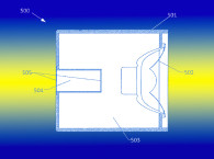
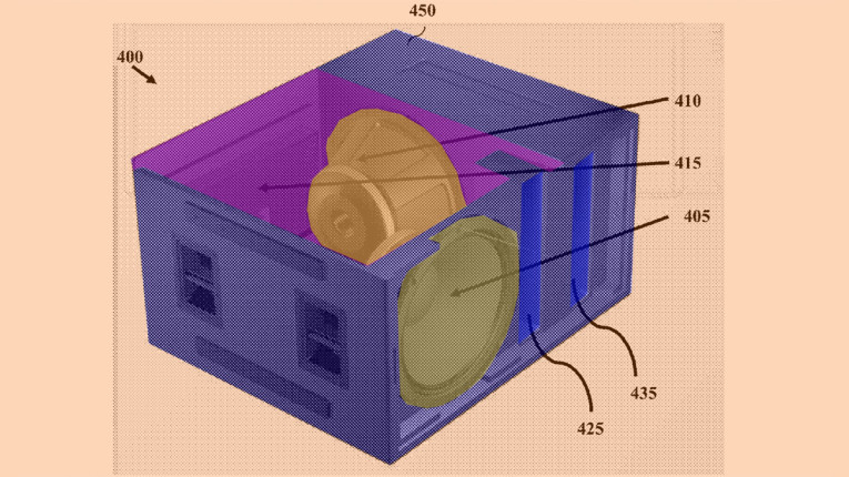
The patent disclosed in this review is one example of an attempt to move beyond the limits of conventional passive or active loudspeakers by turning a passive shortcoming into an active advantage. One aspect of the inventive system is that of combining a parallel, dual-tuned bandpass subwoofer with a full-range, single tuned bass reflex enclosure to form a hybrid, full-range, multi-tuned system (see Patent Drawing 1), but this, in and of itself, is not novel.

In 1972, a decade before Bernhard Puls and Amar Bose developed the original parallel, dual-tuned bandpass subwoofers, Ruben Guss — in US 3,688,864, assigned to Talbot American Corp. — disclosed one of the first examples of a hybrid, dual-tuned bandpass/full-range bass reflex system.
There have been other patents on various forms of hybrid, bandpass/full-range devices, but they have all had inherent shortcomings. A significant limitation with this type of system is that the low-pass acoustic filter of the upper tuning bandpass output (see port exit 135 in Drawing 1) includes the characteristic of an acoustic delay. By comparison, the full-range output from driver 105 of Drawing 1 operates substantially delay-free. Due to this phase difference, the acoustic outputs do not sum as effectively as two woofers would with common input and output relationships to the enclosure (e.g., a simple acoustic suspension or bass reflex enclosure with two identically positioned drivers).
With the delay being caused by a passive, acoustic low-pass filter, as opposed to an active low-pass filter, the drivers are in phase electrically, but somewhat out of phase (constant delay = changing phase vs. frequency) in terms of their external acoustic output into the enclosure and the listening environment. That is why this hybrid, bandpass/full-range enclosure system, even though it has great theoretical potential, historically, has not performed as well as a bandpass or full-range bass reflex system, due to an acoustic loss in output compared to two-driver systems with zero phase difference.
Michael Adams, VP of Engineering at VUE Audiotechnik, is the inventor of the new low-frequency invention of this review. His insight was to utilize the hybrid bandpass full-range system and add signal processing to both eliminate its shortcomings and realize its potential benefits. While utilizing standard forms of equalization, the key element of the signal processing is the application of a delay to the full-range driver (see 105 in Drawing 1) to match the acoustic output delay of the bandpass driver (see 110 in Drawing 1) as it passes through the low-pass filter and delay effects of the combination of acoustic compliance chamber 130 and acoustic mass port 135.
The patent doesn’t specify any parameters for reducing the invention to practice, but if one studies what is written and interprets the concept’s intent, one can glean a pretty good idea from the patent as to what the approach entails.
It appears that by applying delay to the full-range driver a number of effects come into play, depending on the frequency and the enclosure system’s associated function at that frequency. As a reference for the following discussion, refer to enclosure 100 in Drawing 1, and the impedance curve, with curve 1210 representing the impedance of woofer 110 and impedance curve 1220 representing the impedance of woofer 105 (see Figure 1). The two drivers are substantially identical, but positioned with different relationships to the enclosure.

As we start from higher system frequencies (presumably in the 100Hz to 50Hz range for one embodiment) the full-range driver 105 is, for the most part, the only source of acoustic output and the system sensitivity corresponds to the sensitivity of the driver itself.
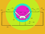
As the operating frequency of the system is reduced to 90Hz, the impedance curve 1210 of driver 110 shows the resonant frequency due to the interaction with the compliance of chamber 130. Going down further in frequency to 60Hz, one can see the resonant impedance peak of driver 105, due to interaction with the acoustic compliance of chamber 120 (influenced by driver 110), along with the anti-resonance impedance dip of driver 110 due to the acoustic compliance of chamber 130 in combination with the acoustic mass of port 135. This is the upper tuning of the dual-tuned bandpass portion of the system. Because the excursion of woofer 110 is minimized at the 50 Hz tuning frequency, chamber 120 exhibits a larger “effective” acoustic compliance relative to driver 105 at the same frequency.
Next, at 48Hz, driver 110 is shown to have an impedance peak due to the “effective” acoustic compliance of chamber 120, which is greater than the actual compliance of the enclosure volume due to driver 105 going into its low excursion, anti-resonance tuning at 40Hz, caused by the “effective” compliance of chamber 120 and acoustic mass of port 125.
Still further down in frequency, at 30Hz is the fundamental anti-resonance tuning frequency of driver 110 as it interacts with the “effective” compliance of chamber 120 and acoustic mass of port 125. Last, at 18Hz and 16Hz, the lowest resonant impedance peaks can be seen for drivers 105 and 110 respectively, due to the compliance of their suspensions, their moving mass, and all the other coupled masses from the ports and chambers.
The interacting relationships, between the drivers and the “effective” chamber compliances, are rather complex. The “effective” compliances are varied from normal dual-driver systems by at least two unique aspects of the invention:
- Due to the delay of the full-range driver to phase match the “external” acoustic outputs, the drivers have different “internal” phases so they are not both compressing the internal air-fluid by the same amount at the same point in time, such that each driver sees a greater acoustic compliance than the half chamber compliance that would normally be seen by a pair of drivers in a conventional system.
- Partly due to the combination of bandpass and full-range bass reflex architectures, combined with the effects of number 1 above, each driver has its resonance frequency substantially coincident with the anti-resonant tuning of the opposite driver, which at least at the upper tuning frequency allows one driver to exhibit anti-resonant tuning frequency and reduced excursion at the same frequency as the opposite driver exhibits its maximum excursion and resonance.
Because of these effects, the system has a number of unique qualities. First, with the differentiated internal phases, the drivers each “see” a combined “effective” acoustic compliance of a virtual enclosure that is larger than the actual enclosure, and the corresponding bandwidth and/or efficiency gains that come from a larger enclosure volume, when the driver parameters are optimized accordingly.
Second, assuming the impedance curve is an accurate representation of a real system, the invention exhibits three tuning frequency excursion minimums at unusually closely spaced frequencies — 30Hz, 40Hz, and 60Hz — reducing transducer excursion and allowing the system to increase acoustic output, with reduced distortion, for a given driver excursion limit. This could be particularly advantageous over the prior art.
Many years ago, your trusty reviewer tested the effects of altering the phase relationships of dual drivers in standard, full-range; acoustic suspension and bass reflex enclosures. At the tuning frequency of the bass reflex systems, it was found that, as opposed to the Adams system, the impedance dip for both drivers remained virtually the same in terms of frequency — suggesting a common tuning frequency for the pair of drivers in the enclosure. But, the acoustic gain at the tuning frequency increased, corresponding to an effective reduction in summed total diaphragm surface area (SD), for the same total enclosure acoustic compliance, acting like a smaller driver operating in an oversized enclosure alignment.
Even though one driver was delayed relative to the other, as in the current invention, the singular tuning frequency corresponded to the same frequency as the two drivers operating with zero phase difference, and where found to be fully determined by the enclosure acoustic compliance and acoustic port mass, remaining independent of the drivers themselves, as would be expected with conventional systems. That would suggest that the lowest impedance minimums and tunings shown in the patent application, being at different frequencies, is a unique and unexpected outcome.
For those interested in the patent prosecution process, unfortunately for the inventor, the patent specification and claims appear to not be as well developed as they could have been. The patent office has rejected all the claims and given a final rejection and another final rejection after an appeal by the inventor and two amendments to the claims. If you look at the claims at the beginning of this review, the underlined portion shows the amended additional claim language, but this language is not supported in the specification, therefore, the patent office has deemed the claim amendments to be invalid. It would seem a shame if such an innovative system would end up not being patentable merely because the patent application was not well developed*.
Early low-frequency systems at VUE Audiotechnik were based on Isobaric-type structures but it appears that four of the later, more advanced systems incorporate the inventive system, which is trademarked as Acoustic Compliance Management (ACM). One can see a little more discussion and illustration of the concept at:
www.vueaudio.com/active-compliance-management-acm.
Ultimately the system is quite interesting in that it provides a unique combination of technology, leveraging an active loudspeaker to greater benefit, and offering real-world advantages. Additionally, one can see numerous ways this concept of, external in-phase and internal out-of-phase relationships, can be extended effectively to other enclosure architectures. VC
This article was originally published in Voice Coil, November 2017.
* This article was updated to reference that the patent was granted in July 2021.