Passive Cardioid Speaker
US Patent Number: US20170353787A1
Inventors: David W. Gunness (Sutton, MA)
Assignee: Fulcrum Acoustic, LLC
Filed: June 3, 2016
Current CPC Class: H04R 1/347 20130101
Published: December 7, 2017
Application Granted: November 06, 2018
Number of Claims: 20
Number of Drawings: 12
Abstract from Patent
A passive cardioid acoustical system, or loudspeaker, is described, which is driven with a single electrical signal and provides a useful reduction of low-frequency sound intensity in the rearward direction while producing relatively high low-frequency sound intensity in the forward direction. This is accomplished by an acoustical circuit which modifies the magnitude and phase of sound radiated by the interior side of a vibrating diaphragm or diaphragms, and combines it with the sound radiated by the exterior side of the diaphragm or diaphragms, so as to cancel part of the rearward radiation and reinforce the forward radiation. The passive cardioid loudspeaker described employs an improved acoustical circuit, which allows improved efficiency, as well as greater flexibility with regard to the size, maximum output, and effective frequency range of the loudspeaker, as compared to prior art.
Independent Claims
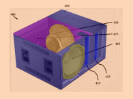
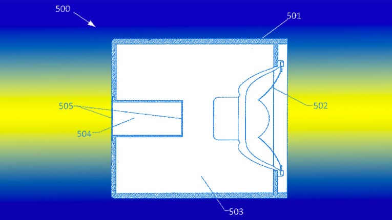
1. A passive cardioid acoustical system comprising: an enclosure enclosing an enclosed air volume; a diaphragm connected to the enclosure and configured to produce sound by vibration; a duct disposed in the enclosure and having first and second apertures; and an acoustically resistive obstruction disposed across the duct; wherein the acoustical system acts as a damped second-order low-pass filter, and is capable of producing a cardioid directional pattern over a range of frequencies.
10. A passive cardioid acoustical system comprising: an enclosure enclosing first and second enclosed air volumes; a diaphragm connected to the enclosure and configured to produce sound by vibration; a duct exiting at or near the back of the enclosure; and an acoustically resistive obstruction at one end of, or within, the duct; wherein the acoustical system acts as a damped fourth-order low-pass filter, and is capable of producing a cardioid directional pattern over a range of frequencies.
15. A passive cardioid acoustical system comprising: an enclosure enclosing an enclosed air volume and having a primary axis; a diaphragm connected to the enclosure and configured to produce sound by vibration; an elongated duct disposed in the enclosure and having first and second apertures, wherein the elongated duct is oriented perpendicularly to the primary axis of the enclosure; and an acoustically resistive obstruction disposed across the duct; wherein the acoustical system acts as a damped second-order low-pass filter, and is capable of producing a cardioid directional pattern over a range of frequencies.


Conventional loudspeakers become progressively less directional with decreasing frequency, such that at the lowest frequencies reproduced by the loudspeaker, the intensity of the sound is substantially equal over an omni-directional radiation pattern. Directivity control for the purposes of environment boundary interaction and listener targeting is a key element in sound quality in both large venues and domestic and recording studio listening rooms.
For upper range frequencies above 700 Hz, with wavelengths of less than half a meter, loudspeaker structures comparable to a wavelength (e.g., waveguide/horns, transducer emission diameter, or baffle size) are easy and practical to apply to achieve the desired directivity control.
For lower frequencies, where the wavelengths are large, and loudspeaker structures need to remain within practical dimensions, other means must be deployed to establish acoustical pattern control. One approach for low-frequency directivity control is that of a multi-transducer gradient system, as often used in microphones, and well characterized for loudspeakers in Harry Olson’s famous Audio Engineering Society (AES) paper, “Gradient Loudspeakers,” presented September 12, 1972, at the 43rd AES convention. While there are nearly an infinite number of variations of a directivity control gradient device, from a first-order, single transducer, bi-directional dipole, to a high-order, end-fire array, with a multitude of sound sources, the more common approach used for low-frequency systems is that of a dual, unidirectional transducer, first-order gradient array.
The basic arrangement is to utilize two unidirectional transducer/enclosures, one behind the other, with the rearward transducer operated out of phase with the front device, and also delayed by an amount that equals the distance between the two transducers. So, from behind the structure, the rear device, due to its delay, acts as if it is at the same point in space as the front device but in opposite phase, creating a null in the output behind the structure.
One example are the cardioid subwoofers made by NEXO of France, with two woofer transducers in each, with the requirement of applying two channels of amplification to be driven by their signal processor with the appropriate delay settings to maximize the cardioid null in the rearward direction. Other companies offer this same kind of integrated system or active controllers with multi-channel amplifiers to be used with two or more of their standard subwoofers in a gradient array.
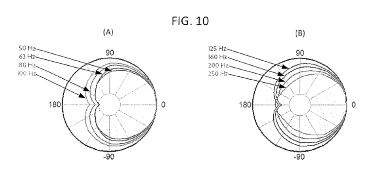

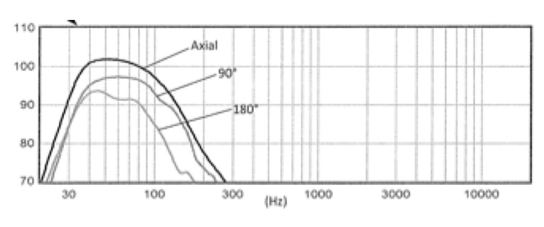
The invention being reviewed here (see Figure 1 and Figure 2 for the patent concept drawings; Figures 3–5 for the example measurements from the patent; and Figure 6 and Figure 7 for drawings of current production examples from Fulcrum Audio) is a simpler, passive form of a gradient system, which is the brainchild of David Gunness of Fulcrum Acoustics, a veteran engineer in the professional audio field, previously with Electro-Voice in the 1980s and later with Eastern Acoustic Devices before co-founding Fulcrum Acoustics in 2008.


The most common gradient polar patterns are usually referred to as bidirectional/dipolar (a figure-8 pattern), Cardioid (a sharp rearward null at 180° from the zero axis), Super Cardioid (sharp rearward nulls at ±126° from zero axis and 115° frontal output), and Hyper Cardioid (sharp rearward nulls at ±110° from zero axis and 105° frontal output). The inventor refers to the polar pattern of the invention as a “Passive Sub-Cardioid,” which does not have sharp rearward nulls, but instead a consistent reduction of 6 dB or more across a full 150° width, centered across the rearward direction from the device, over the system’s full operational bandwidth.
Passive Cardioid loudspeakers tend to be realized most often with one of two configurations. The first, is the combination of an open dipole radiator combined with an omnidirectional radiator, which when summed, create a cardioid radiation pattern. The second approach, of which the current invention is generally based, is a partially open-back, resistive enclosure. The sound emanating from the backside of a vibrating diaphragm has inverse polarity relative to the sound emanating from the front side of the diaphragm, and therefore, if the rear radiation is constrained by an enclosure, but allowed to exit the enclosure through a port located at a distance from the origin of the front radiation; and, if the rear radiation is delayed by an appropriately designed acoustical system, then a cardioid radiation pattern may be produced over a limited bandwidth.
Passive, cardioid loudspeakers of this type have been taught in prior art, such as US 3,722,616 “Directional Loudspeaker System” by Bobby R. Beavers, assigned to LTV Altec, Inc. in 1970, and US 8,428,284, by John Meyer, et al, assigned to Meyer Sound Laboratories. It has also been well explored in literature, as in the 1972 AES Convention paper “Uni-directionally Radiating Loudspeakers” by Wilhelmus H. Iding (of NV Philips) and the 1985 AES Convention paper, “The Acoustic Resistance Box — A fresh look at an old principle” by Thomas Holmes, as well as many more papers.
According to the inventor of the current invention, these prior art devices employ an enclosure with a simple opening and some acoustical resistance to provide an approximation of a first-order, low-pass filter. The phase response of such a filter approximates the phase response associated with time delay, but only at very low frequencies. The equivalent amount of delay provided is directly associated with the corner frequency, f3, of the low-pass filter. The frequency range over which rear attenuation can be achieved is limited to the frequency range over which the phase response approximates delay (<100 Hz in a prior art example); and the distance between the resistive port and the vibrating diaphragm must be chosen so as to obtain the necessary phase relationship between the front and rear radiation. Thus, a loudspeaker constructed according to Beavers and Meyer has limited applicability, due to the limited phase delay obtainable in a given frequency range, and due to the requirement that the distance between the origins of the front and rear radiation be dictated by the available phase delay. Specifically, the prior art is limited to relatively small loudspeakers with limited low frequency extension and output capability.
A second stated disadvantage of the prior art is that a simple opening combined with acoustical resistance may constitute an imperfect low pass filter, so that high-frequency sound impinging on the port opening may radiate through the opening in a direction in which sound attenuation is desired.
A low-pass filter of higher order produces more effective delay for a given corner frequency, and additionally, as is shown in the phase response matches that of pure delay to higher frequencies relative to the low-pass corner frequency.
A limitation of prior art passive cardioid loudspeakers is that at certain higher frequencies, the delay of the rear radiation in the forward direction is equivalent to one half of a period, or odd multiples of one half of one period. Consequently, the response in the forward direction has deep nulls at those frequencies. The frequency of the first null constitutes a limitation of the uppermost usable frequency. Additionally, below a certain lower frequency, the rear radiation propagating forward interferes destructively with the front radiation propagating forward, which limits the low frequency output in the forward direction. Both the low-frequency limit and the high-frequency limit may be shifted up or down in frequency together by changing the distance between the front and rear sources and adjusting the phase-delay to match the change in spacing.
The present invention is intended to address the above state limitations of the prior art, and provides an improved passive cardioid loudspeaker that has the advantage, by comparison, to produce relatively high sound pressure in the forward direction, consistent attenuation in the rearward direction, and improved design flexibility. This flexibility allows loudspeakers of various sizes to be optimized over a wide range of frequency ranges, and allows the radiation pattern to be more effectively optimized to satisfy the objectives of a given design. Compared to the prior art, the present invention provides loudspeakers that are effective at lower frequencies for a given enclosure size, are effective in larger enclosure sizes for a given frequency range, may be used to produce higher output, and may allow low-frequency cardioid behavior in a full-range loudspeaker.
Acoustical systems according to the present invention combine a singular active transducer feeding into an enclosure with an acoustical low-pass output filter of an order greater than one. The acoustical elements consist of one or more ducts, one or more enclosed air volumes, and one or more acoustical resistances applied to the ducts. To provide a low-pass filter with order greater than one, the acoustical system includes at least one enclosed air volume in combination with at least one duct. To provide an acoustical low-pass filter with a desired frequency response, at least one acoustical resistance is provided for the system. In the preferred embodiments, the ducts are generally elongated in shape, though this attribute is not required.
A further aspect of the invention is the addition of a relatively short horn projecting from the forward facing surface of the diaphragm. This horn delays the portion of the front radiation, which propagates in the rearward direction, and increases the directionality of the forward facing radiating surface at somewhat higher frequencies. With appropriate selection of dimensions, this increased directionality allows the acoustical low-pass filter to have a lower corner frequency, which increases its delay, which allows the diaphragm-to-port spacing to be increased, further increasing the forward propagating sound pressure while extending the bandwidth over which useful rear attenuation may be achieved.
In one configuration of the invention an arrangement of elongated ducts lie substantially perpendicular to the primary axis of the loudspeaker, with its entrance located near the back of the loudspeaker enclosure, and its exits located around the perimeter of the backside of the enclosure. This enhancement allows greater flexibility with regard to the acoustical mass of the elongated ducts, the surface area of the port exits, additional delay corresponding to the length of the ducts, and the location of the port exits. The ducts may have various shapes; examples include but are not limited to rectangular and tapered (trapezoidal). Certain combinations of these parameters may be used to obtain uniquely beneficial directional patterns, including patterns that differ from the standard family of Cardioids polar patterns. One such unique pattern provides more attenuation at 90 degrees off axis than any of the standard cardioid forms.
For specialized embodiments, a larger spacing between the front radiating surface and the rear radiating port allows for higher efficiency in the frequency range of interest, but a larger spacing tends to require a longer delay time for optimal performance. Therefore, acoustical filter sections and pathways that provide more delay can be incorporated to improve performance. In addition, acoustical circuits, which provide more flexibility with regard to the effective delay or more precise control of the phase response vs. frequency, can allow for greater optimization of the radiation pattern, including the selection of the particular form of the radiation pattern.
What may have been the most advanced system of this type was developed around 1985 by the late Peter Walker, of QUAD Electroacoustics, Ltd., famous for its world-class electrostatic loudspeakers, the original QUAD ELS (Walker’s Window), and the QUAD-63, both with dipole, figure-8 radiation patterns.
As one of his last design projects, Walker developed an electrostatic loudspeaker mounted in a spherical enclosure, 20” in diameter. The electrostatic panels mounted on the front face of the sphere incorporated passive (LC networks) delay rings to maintain constant dispersion over the frontal radiation angle (as used in the QUAD-63). Two more electrostatic panels are mounted behind the front panel, each passively delayed to align with the front panel as the radiation source plane. The rear of the spherical enclosure included four resistive ports, arranged in a square, that when combined with the internal structure could provide a precise phase vs. frequency control that allowed a more effective cancellation of the rear wave over a wide angle and frequency range.
The resulting cardioid radiation pattern was unique in maintaining a hybrid subcardioid/semi-dipolar pattern of suppression of approximately -12 dB from +100° to -100° across the rear of the device, relative to the zero axis reference output. That is an unusually effective cardioid pattern to maintain over the bass and lower midrange of the device without any sacrifice in efficiency while exhibiting one of the most effective room interaction directivity patterns possible.
There were 22 prototypes built of this spherical electrostatic, affectionately known at QUAD as “Peter’s Balls.” They were never put into production, due to domestic concerns about people being willing to place two room-dominate spheres in the living room, and also the fact that the company was falling on hard times and about to be acquired. The recipe for the design is now held by the Chinese company (International Audio Group) that currently owns the QUAD name and intellectual property.
The current Gunness invention of this review appears to have similar advantages over the prior art as the Walker electrostatic version does, while providing a more simplified construction. Of the four standard cardioid shapes, the subcardioid is the most efficient at low frequencies. By targeting consistent attenuation across the back hemisphere instead of trying to achieve a deep null somewhere, higher sensitivity can be maintained at low frequencies. The system tends to not only have greater low-frequency extension and efficiency for a given enclosure volume but also greater large signal capability for a given driver area and excursion capability as compared to other cardioid formats.
When well designed, above the cutoff frequency of the acoustical low-pass filter, the rear radiation ceases and the loudspeaker transitions to the natural directionality of a forward facing driver and baffle. In this frequency range, the polar pattern of the forward radiating sound source in the enclosure is optimized to be similar to a subcardioid pattern. When the design variables are effectively coordinated, they can be adjusted to change the shape of a passive cardioid’s polar response, and a more consistent spectrum can be achieved over the entire sound field.
Another advantage of this type of passive subcardioid over the more complex dual driver, active cardioid system is that the standard system has the hyper null in the rear output at the lowest frequencies but not at somewhat higher frequencies, which results in the distortion component not being cancelled as well as the fundamental, and the acoustical output from the rear of the device can exhibit greater audible distortion. An additional attribute of the subcardioid approach is that when used in arrays, the rear attenuation increases, which can be advantageous in reverberation reduction and intelligibility in large venue applications.
Having worked with optimizing these type of systems in the past, it has been observed that half the performance is due to the type of system with the most effective architecture, and the remaining determination of performance is due to optimizing all the little interactive variables, which can be time consuming but also quite rewarding in providing an increase in performance.
Gunness has come up with what appears to be a very effective configuration, and I am pretty sure that after developing a number of production units as he has done, he has learned many little secrets, that aren’t mentioned in the patent, that allow a more ideal optimization of the device. The invention appears to be a very good design that should advance the art in the category of cardioid devices.
Last, as is often the case with ungranted patent applications, the patent examiner has identified a prior art patent, US 4,054,748, “Cardioid Electro-Acoustic Radiator” by Geza Balogh, from Budapest, Hungary, assigned to Electroakusztikai Gyar, that incorporates the multi-pole low-pass filter on the rearward output from the enclosure, which the patent examiner has asserted as prior art that anticipates the Gunness design and has issued a first non-final rejection of the application.
At the time of publication Gunness has submitted his arguments and is awaiting the next examiner response. (Update: the patent application was granted November 06, 2018. James Croft reviewed the published patent in the Voice Coil February 2022 issue, as promised in his original article). VC
This article was originally published in Voice Coil, February 2018.