Egg Speaker Design and Construction
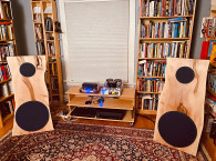
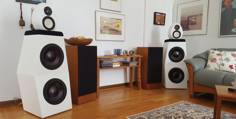
First, I made a deviation in the woofer section. I did not want as much footprint as Tom’s pyramids presented. That fit right in with the learning I had hoped for in this project. I’ve never designed a speaker and frankly have been intimidated by some of the design ingredients, if you are going to go about it in a serious way. Vance Dickason’s Loudspeaker Design Cookbook had sat on my shelves forever and now it was time to read and understand and apply it. I would design my own cabinet to meet a set of criteria, still using the same Dayton Audio RSS315HO44 12” woofers from the Egg design. I won’t dwell on the midrange and tweeter egg section, having pretty much followed Tom’s construction descriptions and using the same Satori TW29BN-B beryllium dome tweeters and MR16P-4 midrange drivers. Photo 1 shows the finished product in place, flanked by the CS7s, which were about to be replaced.
Woofer Section Design
The design process began with a combination of a rough footprint, desired height (with the egg section still designed to sit on top), and a mental image of shape, admittedly somewhat influenced by the venerable Waveform Mach 17s. The next step was to apply some of the design theory to determine a required volume. It’s an iterative process given the footprint and size constraints vs. the resultant performance. This was accomplished using the published speaker parameters of Fs, Qts, and Vas to calculate Qtc, Vc, and Fc for a range of Vc ft3 values from 1 to 5 (Table 1).
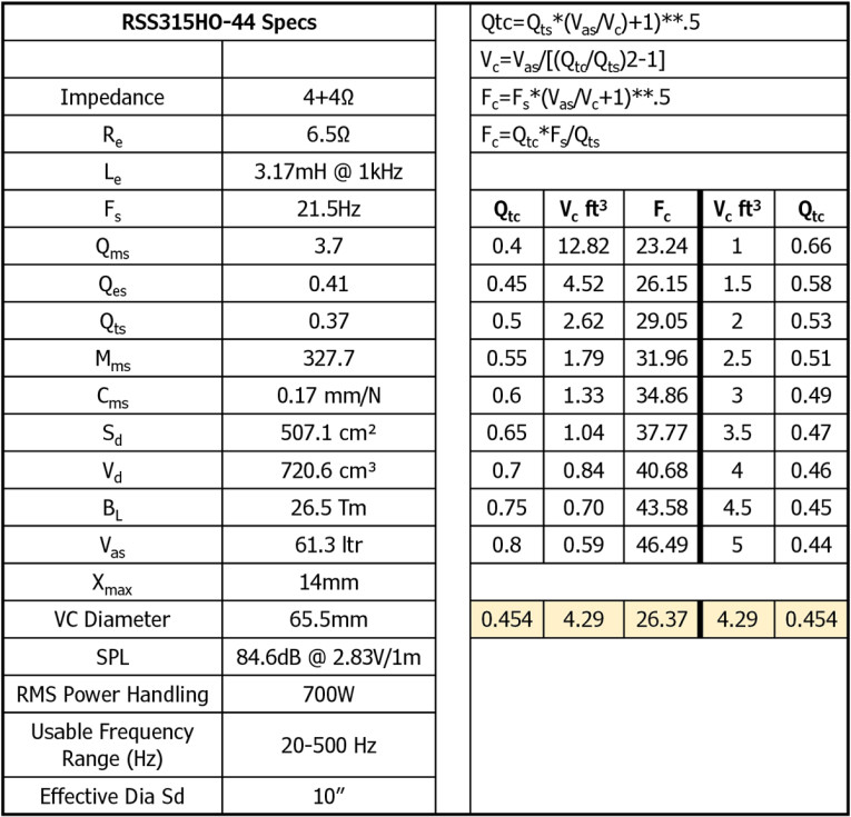
From here, it was a matter of deciding the trade-off of low frequency cutoff vs. tightness of bass desired, leading to a compromise volume around 4.5ft3. The shape I had in mind was for an upper and lower section of a relatively rectangular and columnar approach, the lower section slightly canted upward, and the upper facing straight into the room. I also wanted complimentary slight angles to break up what would otherwise be straight sides.
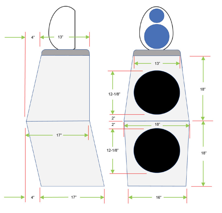
Initially, I built some 3-D models, but somehow I wasn’t quite satisfied with the visualization of the actual look. So instead, I built some full-scale models with duct-taped cardboard, which turned out to be quite effective. It also allowed my wife to add her approval to what would eventually be appearing in the living room! Figure 1 shows the dimensional result after playing with variations of the dimensions in a spreadsheet that calculated volume, and until the look spoke to me on paper and with the cardboard models, and the volume matched the Vc ft3 calculation. For the dimensions shown and built, the internal volume is 4.29ft3. The row highlighted in yellow in Table 1 shows the Qtc at 0.45 and the Fc of about 26Hz that result from this volume. That should provide a decent bass extension with reasonably tight response.
That said, I was now faced with the challenge of cutting wood to meet the design plan. If you’ve ever built a wood project with multiple odd angle intersections, you know that determining the cutting angles can be daunting. Fortunately, I didn’t need to haul out any dusty math books or make my brain hurt too badly! There are several excellent online angle calculators for exactly this kind of wood cutting, one of which did me great service. Still, laying out those angles on the many pieces of wood and setting the saw appropriately over and over still left plenty to do and several trials and errors to get it right.
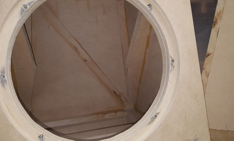
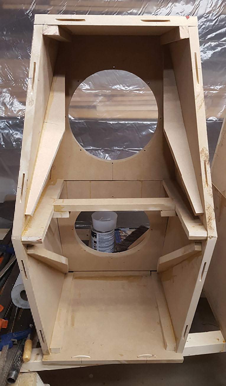
Five pieces constitute the bottom section, and five more for the top. I doubled the thickness of the front two pieces to facilitate routing for speaker mounting the drivers. All the pieces were joined with biscuits and wood glue in multiple clamping operations. For ease of clamping and alignment, the top and bottom sections were assembled separately, (Photo 2a) then joining top and bottom together. Rough completed assembly (Photo 2b). Finally, all but the front boards were re-enforced with glued in braces (Photo 3).
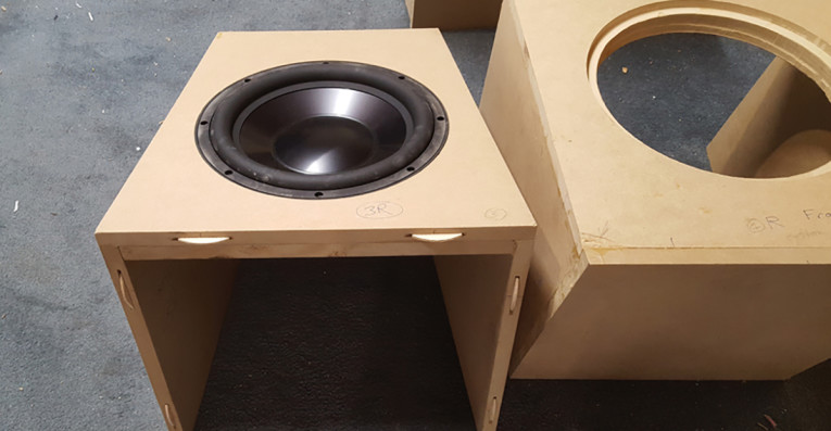
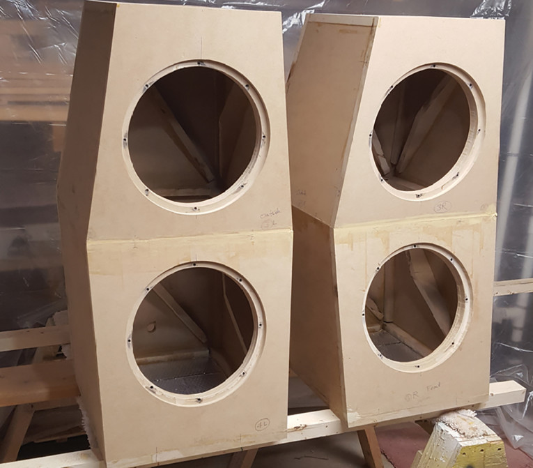
Photo 2: For ease of clamping and alignment, the top and bottom sections were assembled separately (a) then joining top and bottom together until I had the rough completed assembly (b).
Sanding the board intersections followed by router ½” quarter rounding and lots of finish sanding brought the process up to the paint stage. I preceded the white paint finish with a coat of sprayable polyester filler, which eliminated any residual texture of the MDF and prevented any differential absorption of the finish coat. A fine sanding produced the desired final uniform and matte finish look.
Crossover and Amplification
The two crossover frequencies chosen were 200Hz and 2500Hz. I began with a passive crossover network based on Tom’s article and my existing 250W amplifiers. The results were not as impressive as I had hoped. As the passives have a number of limitations and are expensive and painful to iterate changes, I quickly concluded that I would for the first time try the active crossover tri-amp route. The first attempt was with a three-channel analog filter with individual gains and two crossover frequencies, set by plug-in filter components. This didn’t yield an overall flat enough response or satisfying sonic performance either for even my not-so-golden ears.
Time to take one more step into modernization with a DSP crossover. The one I chose as a compromise of features and cost is the miniDSP 4x10HD. It has a substantial set of direct filter frequency and gain adjustment capabilities as well as multiple byquad IIR filter sections that can be fed parameters from several analysis programs. For initial tests, I used three separate amps I had lying around. From the speaker efficiency data and some initial mid-band measurements, referencing to the woofers (they being the least efficient), the midranges needed an input level of -13dB and the tweeters -14.5dB. Programming those gain factors and the crossover frequencies into the miniDSP 4x10HD, I was finally making progress toward acoustic results I liked and that started to measure well.
Amplifier Decisions
Given the above driver input levels and assuming, say 1000W for the woofer section, the midrange requires only 46W and the tweeter 35W to simultaneously reach the maximum output level. Clearly the pile of equal power mono-blocks was not optimal. So, the goal became to also build a dedicated six-channel amplifier, with a pair of higher-power channels for the woofers and identical four lower power amps for the mids and tweeters. Additionally, I wanted a reasonable size and weight package, with the amplifier performance best matched to each driver type.
Amplifier Design
Nowadays, the necessary high power for the woofers is most easily achieved with Class-D amplifiers, with the side benefit of substantial weight reduction. There are a number of Class-D designs available that also have excellent frequency response. I chose a pair of Purifi Audio 425W Class-D amps. Although the RSS315HO44 12” bass drivers are rated for 700W each, so theoretically capable of accepting up to 1400W each channel, I decided 425W would be enough, a good compromise between SPL and minimized footprint, weight, and heat for the bass channels.
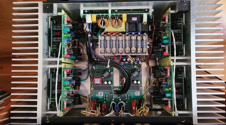
These modules were discussed in an Industry News item on the audioxpress.com website, “Purifi Audio Promises to Reduce Distortion in Speakers and Amplifiers,” in April 2019, and reviewed by Ward Maas in the July 2020 issue of audioXpress. The modules impressed me back then with their design approach and exceptional performance. Purifi Audio offers an evaluation kit that consists of a pair of the amp modules along with a shared common low voltage power supply and gain sections, all in a remarkably small footprint (Photo 4 and Photo 5). They incorporate a back panel that includes a set of RCA and XLR balanced inputs, as well as standard ¾” spaced banana jacks for the output.
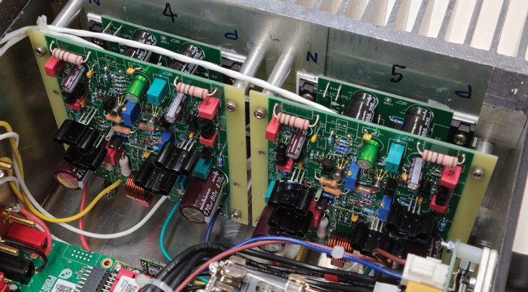
The goal for the midrange and tweeter channels was to stay with Class AB and to have performance worthy of the outstanding Satori drivers. While I’ve designed a number of FET-based power amplifiers over the years, I was impressed by Bob Cordell’s retrofit design for the venerable Hafler DH-220 and DH-230 amps, as recently featured in the July and August issues of audioXpress. PCBs are available for them on eBay (see the Parts List), making the build a whole lot easier than rolling a new design of my own, and their performance and low noise levels put them in the quality class of the driver elements. While physically targeted for the original Hafler amp cases, the form factor of the Cordell DH-230 amps was ideal for the enclosure I was envisioning.
When ordering these on eBay, you will receive the bare PCBs and detailed support for ordering parts, including prepared order sheets for two parts supply houses. Finally, to keep things light, I chose a pair of switching power supplies to complete the assembly (Photo 6). The Purifi Class-D amps are powered from a 1200W Hypex SMPS1200A400 power supply, capable of feeding both of the 425W amps to simultaneous continuous full output. The four mid and tweeter amps are powered by a 400W Hypex SMPS400A400 power supply. The latter will clearly not enable all four amps to deliver their 200W simultaneously, but in practice the power required to drive the speakers is maximum in the neighborhood of 20W per midrange and 15W per tweeter. These amps will be loafing, but were chosen specifically because their performance is so exceptional, including when operating at low power output!
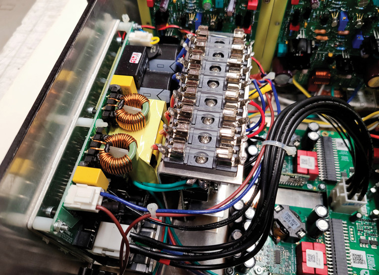
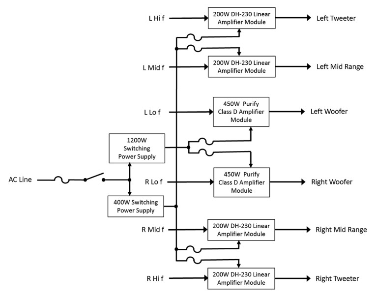
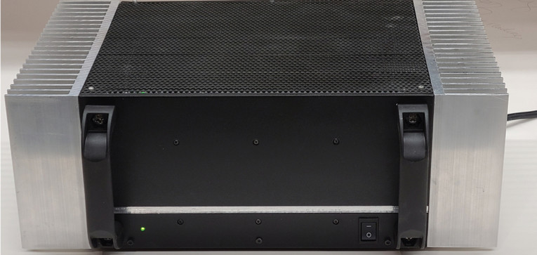
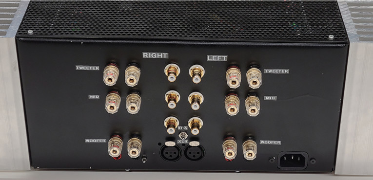
Figure 2 shows a block diagram of the six-channel amplifier. Each amplifier is separately fused at the DC input side. The physical design is anchored by a pair of 6” tall Wakefield 510 heatsinks on the sides and a thick aluminum front plate that serves double duty as the heatsink for the 1200W switching power supply (Photo 7). The back panel (Photo 8) mounts the Purifi I/O, 6 RCA inputs, and six sets of gold binding posts for the speaker output.
Crossover Tuning
Tests and measurements were done with the Dayton OmniMic speaker measurement system. The initial programming parameters I used for the MiniDSP were crossover Linkwitz-Riley fourth-order crossover frequencies of 200Hz and 2500Hz, and attenuation factors of 0dB for the woofers, -13dB for the tweeters and -14.5dB for the midranges. Initial listening and OmniMic scans suggested the need for an additional -6dB filter at 2kHz to suppress a slight nasal intonation as a tuning starting point.
Further Tuning and Performance
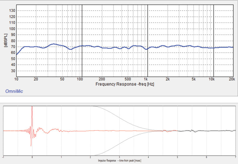
Figure 3 shows the measured frequency at the typical listening position with 1/12th octave smoothing, and the impulse response measured 5’ in front of the speaker. Beyond the crossover filters, frequency response compensation at this point consists of several manually generated IIR filters using the miniDSP plug in application. Notably, very little compensation was required to flatten the high end, and no boost filtering whatsoever was applied at the low end. The flat extension down to around 12Hz or 13Hz is innate, which took me quite by surprise given the driver’s Ft around 20Hz. Room location with the speaker a foot in front of the wall is responsible to some extent. In any case, the low end is definitely for real as witnessed by the ability of these speakers to shake the walls and floor!
I have not yet run REW to generate room compensating filters beyond my manually generated ones. So far, I am very impressed with the performance of these speakers and can listen to them for hours as is. Sorry, I’m not going to get all flowery and unbelievable about soundstage, imaging, and transparency at this point, but I will say the bass performance of the Dayton Audio RSS315HO44 drivers is astonishing. My wife says she can always tell when I have played them loud while she was gone because all the pictures in the living room are hanging crooked!
Next Steps
I plan to do further tests and filter tuning including variations in crossover filter parameters, adding delays determined from driver measurements, and crossover designs with less steep attenuation as well as alternative use of shelf filters. The goal being improvements in phase linearity and better time alignment. This should enable achieving a cleaner impulse response, and thus yet better imaging and rendition of the original performances.
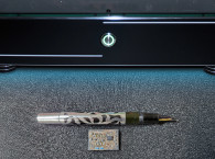
One additional design element: When it came time to run wires from the amplifiers to the speakers, the shortest and neatest route was through the floor and across in the basement. Given the thickness of good speaker cable, I was not happy with the idea of drilling large holes in the floor. The solution was to drill smaller holes through the baseboard quarter round and lining them with brass tubing sized and spaced for standard banana plugs. On the living room side, these give a neat appearance (Photo 9), and in the basement, the speaker wires are crimped and soldered into the brass tubes. aX
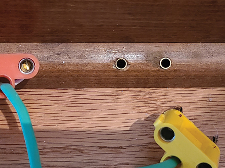
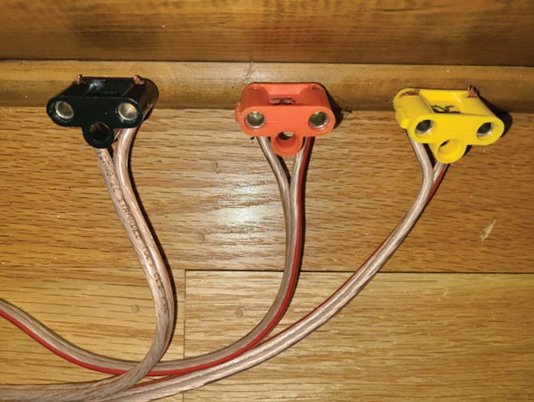
Photo 9: On the living room side, these give a neat appearance (a); and in the basement, the speaker wires are crimped and soldered into the brass tubes (b).

Resources
B. Cordell and R. Savas, “The Dh-220C MOSFET Power Amplifier,” (Part 1): The Circuit, audioXpress, July 2021
B. Cordell and R. Savas, “The Dh-220C MOSFET Power Amplifier,” (Part 2): Construction and Testing Instructions, audioXpress, August 2021
W. Maas, “A Visit to Purifi Audio: Where the Magic Happens, audioXpress, July 2020.
T. Perazella, “The Incredible Egg (Part 1): Sound Reproduction at Its Best,” audioXpress, September 2018.
T. Perazella, “The Incredible Egg (Part 2): Assembling the Eggs,” audioXpress, October 2018.
T. Perazella, “The Incredible Egg (Part 3): The Proof Is in the Listening,” audioXpress, November 2018.
V. Dickason, Loudspeaker Design Cookbook, 7th Edition, 2006, available from KCK Media, cc-webshop.com
This article was originally published in audioXpress, July 2022
 About the Author
Reinhard Metz received his BSEE and MSEE degrees from the Illinois Institute of Technology and University of Illinois/Champaign respectively. He worked for 29 years as an engineer and manager at Bell Laboratories before starting an engineering and legal consulting business. He then joined CookTek LLC. where he specialized in power electronics for commercial induction cooking equipment and became V.P. of engineering. Now retired, he has had the opportunity to return to his life-long audio hobby, including the design and building of FET power amplifiers. He has published 27 papers and articles in the areas of Telecom, audio, and general aviation. Aviation being his other consuming hobby, he flys a four-seat fiberglass high-performance airplane, which he built himself. He has 18 patents and three pending.