From 2010 to 2015, the US voice coil winding industry was slowly and painfully decimated. The bulk of the speaker assembly industry moved to Asia or to Mexico, but the last few domestic coil winders hung on as they offered extremely high power coils, high-aspect-ratio flat wire coils, or other unique attributes. Eventually, the top coil winders in Asia acquired most of these capabilities. Today, only Precision Econowind remains in the US, both to wind and supply its high-performance voice coils. The company also serves as the agent for Poyun’s off-shore voice coils. In any case, we have not published a tutorial on coil winding in Voice Coil magazine in five years, so here we go.
Voice Coil Basics
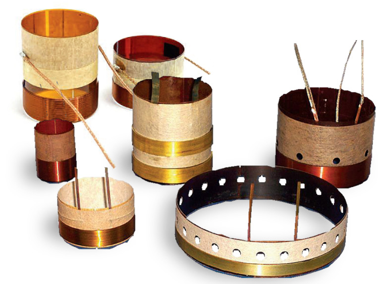
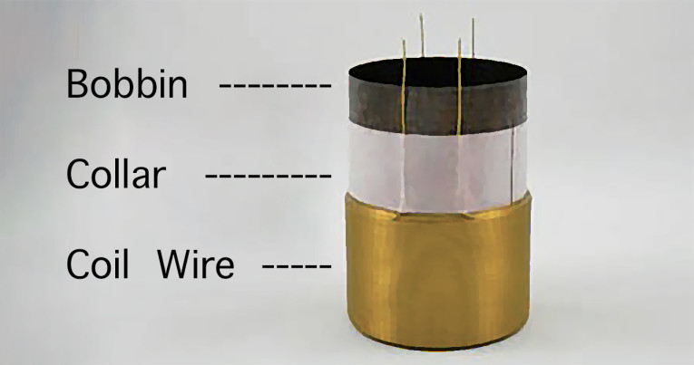
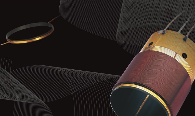
The typical speaker voice coil has less than a half-dozen components: the bobbin, the wire, the collar, adhesives, and the lead-out wire. The voice coil starts out with a die-cut, pre-coated with adhesive blank, onto which is the voice coil wire is wound. The form factor of the bobbin blank will depend on many factors. Of course, the bobbin’s diameter is dependent on the voice coil gap diameter. The clearance specified from the pole piece to bobbin is usually less than the clearance specified from the coil’s outer diameter to the top plate. Pole piece to bobbin rubs are less damaging than coil insulation to top plate rubs and accommodate the coefficients of coil’s expansion due to heating.
The height of the bobbin depends on numerous factors including:
• The voice coil winding height
• The distance between the top of the voice coil stack to the spider. The distance between the top of the coil and the spider provides the clearance needed to prevent the spider from contacting the basket/top plate on downward strokes. Typically, this dimension is actually the byproduct of the particular cone and speaker basket selected.
• The distance the bobbin extends beyond the neck joint and cone apex attach. If the bobbin extends too high, then a larger or deeper dust cap must be used.
Winding the voice coil entails placing the blank onto an arbor, forming it into a cylindrical bobbin, and winding wire onto the form. As the coil is wound onto the bobbin, the insulation coating (and the thermoset adhesive coating on the blank) is activated with MEK, alcohol/acetone or another solvent system.
Alternatively, wet winding wire techniques are used, usually for very high power voice coils. In this case, the adhesive is applied to the insulated, non-adhesive coated magnet wire as part of the winding operation. The entire voice coil assembly is then cured. Traditionally, the coil is baked to snap-over the thermosetting glue forming a molecular cross-linked bond. Baking time is going to be longer than the stated adhesive cure time and will depend on the American Wire Gauge (AWG) number, which might range from #35 to #28, and the number of layers, from single-layer flat wire to four layers (or even eight layers).
To provide a rough guide, if the adhesive nominally requires 25 minutes at 425˚F, then a small coil (small gauge/small diameter) might be baked for 30 minutes at 425˚F. A large 3” to 4” diameter coil can require 80 minutes at 450˚F. Finished voice coils wound on bobbins are available and numerous suppliers are listed in the Voice Coil Winder directory published every year. Alternatively, speaker manufacturers bringing the process in-house might start with the coated blanks and wind either directly onto the bobbin or bond the bobbin to a ready-made coil stack, which is sliced (this is more common in flat wire voice coils).
Adhesive considerations for attaching the voice coil/bobbin to the spider and cone are many. Considerations of cost, temperature capabilities, ease of application, cure time, bond strength, and the effect on frequency response must be traded off for the best compromise for a specific application. Regardless of bobbin material, in applications where the speaker will be subjected to a high-power operation on initial use, the coil assembly should have a final low temperature (150˚F) bake for 12 hours to enable a slow controlled out gassing. This will eliminate blistering in the wire insulation and between the coil and bobbin.
Voice Coil Considerations
Specification Blanks — Let’s drill deeper on the bobbin substrate materials, which starts off with the some considerations for the required/desired strength, mechanical and electrical properties, and temperature tolerance. The outside face of the blank is coated with a thin film of B-staged thermoset adhesive. Blanks are often purchased pre-coated from a “converter,” which is a firm that both coats and slits, as well as stocks and distributes voice coil winding materials (some converters are listed in this month’s directory).
Coating and Converting — Coating thickness is a factor in total film thickness, but should be separately specified from the film substrate itself. For bobbin thickness, 1 mil or 2 mil bobbins are used where mass/thickness are critical (e.g., in tweeters), and 2 mil and 3 mil is ideal for standard automotive loudspeakers. The 3 mil bobbin thickness is popular for many consumer audio applications (e.g., soundbars and smart speakers), while 5 mil is used where wall strength is critical (e.g., higher output speakers, especially woofers).
Bobbin Configurations — Bobbins might have spiral or butt joints. In the latter case, there is a slit or gap in that joint. Depending on the voice coil diameter, the butt gap is typically 1/64” to 1/32” wide. This gap will expand during high-temperature operation of the voice coil. Spiral bobbins have been used to improve the roundness of bobbins where tight voice coil gaps are required.
At first glance, non-electrically conductive bobbin substrates do not require a gap as overlapping will not create a shorted turn. Shorted turns with electrically conductive materials result in inductive effects, such as high eddy currents, higher distortion, rocking of the coil, and heating. There are many superior speakers with aluminum bobbins, with the design using eddy-current canceling techniques (copper cap, shorting ring) to avoid distortion while increasing damping. Nevertheless, most bobbins are split to accommodate thermal expansion of the voice coil.
Bobbin Venting — Some speaker engineers use holes punched into the bobbin between the top of the voice coil stack and the neck joint. Primarily, this technique is used to improve cooling. Air cavity pressure buildup may be reduced behind the dust cap with this form of bobbin venting. Other positive effects are mass reduction and dampening torsional bobbin resonances. One not so attractive effect is the nasty turbulence “whistling” that can result if the air velocity is too great through the vents or if the vents become partially blocked on large excursions. If the vents are too large, then the structural integrity of the bobbin could be compromised and buckling may result.
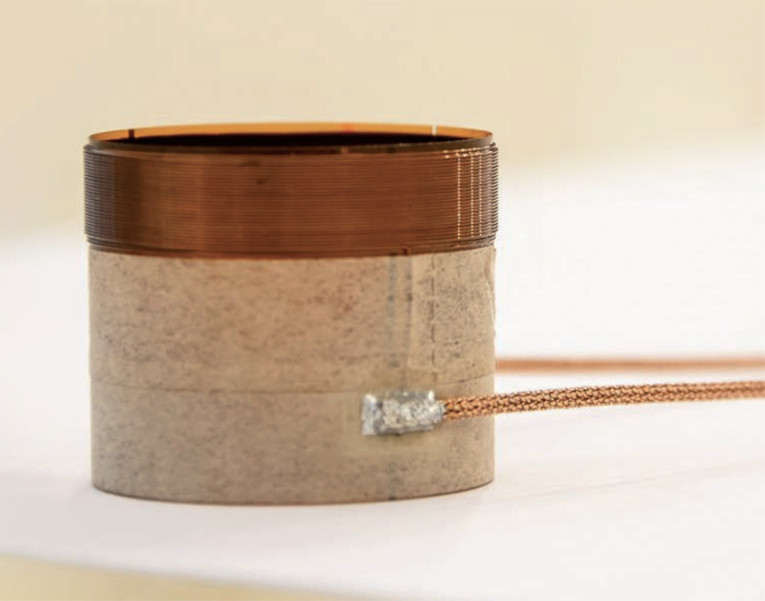
Collars — A collar is one or more turns of a band of material located between the coil stack and the neck joint. Often, the collar extends into the neck joint. Primarily, the collar is used to properly dress the lead-out wires from the coil, but lead-out wires may also be glued directly to the bobbin.
Secondary features of collars are to enhance adhesion and maintain roundness. Additional purposes may include added bobbin wall strength, temperature insulation between the bobbin and the cone, and as a correction factor for fitting bobbins that are slightly too small for a stock cone I.D.
Thermal Considerations — Aluminum bobbins are popular due to high thermal transfer but might result in excessive heat to the neck joint, not only due to their thermal conductivity, but also due to self-heating effects from the eddy currents. If high heat is anticipated at the neck joint, this may require compromises in the selection of adhesives.
Additionally, the eddy currents are not uniform along the width of the bobbin due to divergence of the induced current at each end of the sheet. This results in a tipping or canting force induced on the voice coil that is proportional to the cone velocity.
Thermoset polyimides are significantly lower in mass than aluminum, and as they are not electrically conductive, will not short out the voice coil in case of insulation failure between the coil and the bobbin. DuPont Kapton, UBE Ulpex and Kaneka Apical are the leading suppliers of thermoset polyimides (PI) and not to be confused with thermoplastic PI, which is often supplied by Chinese voice coil vendors.
The thermoplastic films go soft at higher temperatures and can result in “coil shucking” and bobbin deformation at much lower power levels than thermoset PI. Fiberglass and composite materials have also been used on bobbins for high-power woofers and sub-woofers with good results.
Wire Considerations
Magnet Wire — Magnet wire is available in a wide range of sizes, cross-sectional profiles, and wire insulation coatings. The insulation layer is called the base coat and is available with an adhesive bond, which is the top or outer bond coat. Magnet wire is often pre-coated (green = dry but not cured) with an adhesive that is reactivated during winding (typically with 10 parts MEK or alcohol to 1 part adhesive). Alternatively, the wire can be wet-wound, with the top-coat adhesive applied to the non-adhesive coated wire during the winding operation.
The wire gauge, often referred to by its AWG designation, is selected by a number of factors, including desired DC resistance, mass considerations, (current) power handing, and magnetic system considerations. A high-power subwoofer might use a gauge as heavy as #28 AWG, while a super tweeter might use a wire gauge as fine as #38 AWG. Fine wire is considered 34 AWG to 44 AWG. Note that with AWG, #32 AWG has twice the diameter of #38 AWG, #26 AWG is twice the diameter of #32 AWG, and so on. Every six sizes increases the current capacity by a factor of 4, and every three sizes increases the capacity by a factor of 2. Conductor material considerations aside, strength is directly proportional to the cross-sectional area of the wire.
Copper wire is most commonly used for speakers, although aluminum and copper-clad aluminum wire (CCAW) are also used. Copper is more conductive than aluminum and substitution of aluminum for copper requires a larger diameter wire for the same conductivity. Copper offers superior strength and is much easier to solder to than aluminum. New alloys are in development that will offer advantages over existing conductors.
Wire Joining — Joining lead-out wire to aluminum voice coils requires special fluxes or mechanical (crimp) connection techniques. Aluminum offers lower mass with greater conductivity per unit weight than copper. Aluminum wire is vulnerable to work with—hardening when used at elevated operating temperatures, resulting in brittleness and wire failure. Furthermore, aluminum expands over one-third more than copper when subjected to the same temperatures. CCAW offers much of the benefits of both materials, but is still not as robust as copper wire.
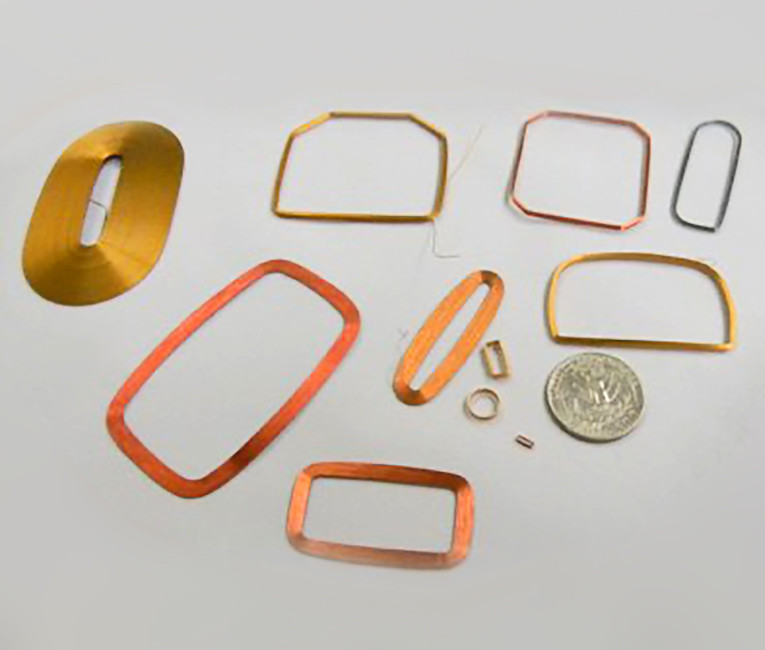
The wire may be flattened to various aspect ratios, with 4:1 or 5:1 being the most common, with the state-of-the-art reaching 7:1 and beyond.
For the highest performance and to achieve radical wire aspect ratios, the wire can be flattened and then coated with insulation. This requires full magnet wire production capability. A recent trend is square wire, which provides the higher wire density (cross-sectional mils of conductor) in the gap, yet avoids the problematic single-layer flat wire return wire.
Wire Insulation — There are many types of wire insulations offered for magnet wire, with characteristics optimized for transformers, relays, clocks, motors, generators, and so forth. For loudspeaker voice coils, the field narrows but there is still a large selection. For high power speakers, magnet wire targeted toward inverter electric motors is worth checking out.
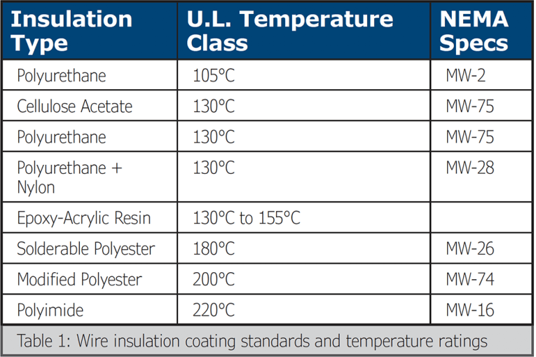
There are quite a few wire insulation formulations and designations, which include the Underwriters’ Laboratories (U.L.) Recognized Temperate Class and the National Electrical Manufacturers Association (NEMA) Specification (see Table 1). Some of the more advanced coil winders have their own formulations.
In production, 220 C insulation will not burn off when you attempt to terminate (solder) the coil winding, so an abrasive or chemical operation will be needed to take off that tough insulation. Of course, if you are building expensive and high-power speakers, this is a small price to pay.
If high temperature operation is not likely, then coil termination assembly procedures can be simplified with a 130˚C (typically Nylon-poly) or 180 SV C insulation. Wire manufacturers classify insulation removal into three classes —solderable (the wire insulation disintegrates during soldering); removable by reagent or other chemical process; and mechanical (i.e., abrasive method).
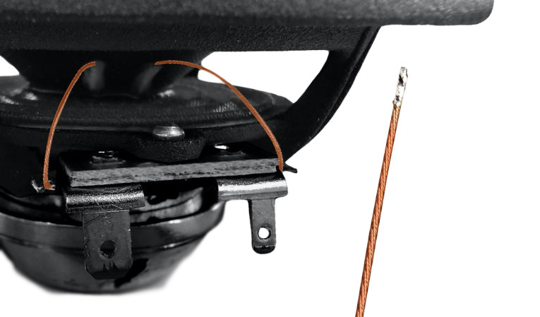
Load-Out Wire — Load-out wire types vary depending on the speaker. There are many choices of braided wire, with variations in gauge or fabric strands woven in with the wire. Alternatively, in high-powered tweeters and compression drivers, flat conductor strips are sometimes used with phosphor bronze or Beryllium alloy. Various wire dress options can be selected for the lead-out wires, including wire spacing and the use of a collar between the coil stack and the neck joint.
Wrap-Up
I always find it challenging to provide a comprehensive tutorial along with some caveats without going off onto a tangent. Most of the individual topics could easily be a complete article. I hope to have exciting voice coil news next year as there are game-changing developments in magnet wire coming from electric vehicle motor research. VC
This article was originally published in Voice Coil, August 2020.