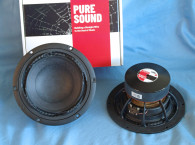
The cone assembly consists of a flat profile paper cone made with a proprietary fiber mix, a 2.4” concave dust cap that covers about 90% of the cone surface, plus the addition of a V-shaped edge reinforcing ring glued around the outside rim of the back side of the cone (Photo 2). This reinforcing ring makes the cone edge extremely stiff, and would appear to severely dampen cone edge resonances.
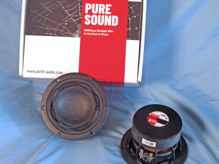
Compliance is provided by NBR surround, which like the PTT6.5X surround, is an entire story in itself. Looking at Photo 1 and Photo 3, this is a genuinely unique construction. The surrounds, besides providing compliance and centering, are indeed a source of noise and distortion as well as a tool for damping a cone’s outside rim. It is not a surprise that surrounds have been the subject of numerous patents that offer solutions based on shape, material, and complex material thickness, but I have yet to see anything this articulated.

The PTT4.0X, like the PTT6.5X surround configuration is a combination of alternating sections of both reverse roll and positive roll, plus some interesting undulations within the alternating sections. Note that the positive roll has an obvious left/right asymmetry, which yields a positive/negative going articulation on either end of the reverser roll sections. Purifi Audio’s co-founder, Lars Risbo, made the following comment about Purifi Audio’s surround technology:
“The surround geometry serves multiple purposes: The strange shape ensures that its radiating area Sd is kept constant over its full stroke (eliminating a strong IMD source). It further tames the usual cone edge breakup (together with the stiffening ring below the cone edge) and is very resilient to the back pressure from a small box. Finally, it is excellent at keeping the coil centered even at large excursions. The combined result is that the IMD hovers around the theoretical Doppler limit.”
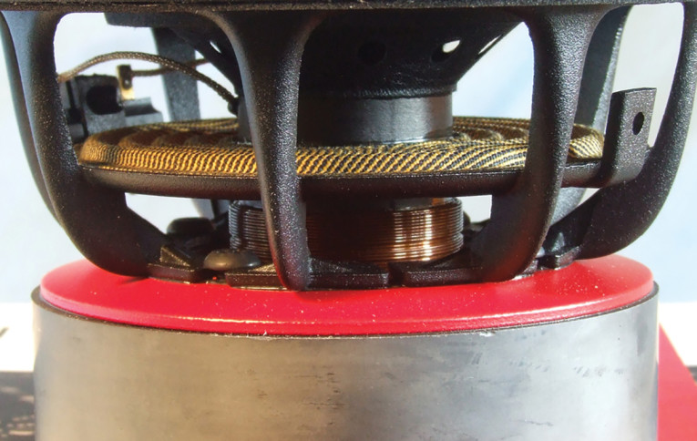
Remaining compliance is provided by a 3.5” diameter symmetrical roll flat spider (damper). The motor consists of an FEA-optimized 88mm×25mm ferrite ring magnet with milled and tapered plates, the frontplate having a red coating and the backplate having a black emissive coating, plus a pole piece comprised of a neodymium pole magnet sandwiched between steel sections that serves to linearize the Bl. Driving the cone assembly is a 30mm (1.18”) diameter four-layer voice coil wound with round aluminum wire on a non-conducting fiberglass former. Like the surround, this four-layer coil also exhibits some very unique engineering. Unlike a winding that has the same width across its full length, this four-layer coil has alternating two- and four-layer sections on the length of the coil with varying widths of two- and four-layer sections as seen in cutaway rendition in the Photo 4.
As can be seen in Purifi Audio’s motor rendering, most of the pole (3) is replaced by a strong neodymium magnet: This reduces the coil inductance significantly as well as the inductance vs. position gradient all the way to DC (this cannot be achieved by shorting rings since they only work above a certain frequency determined by the their cross-sectional area). An iron pole piece extension (hat) (4) is optimized to flatten the inductance vs. position further. This virtually eliminates the current dependency of the Bl factor as well as the position dependency of the coil impedance—two major nonlinear sources of especially intermodulation distortion (IMD) (changing the Bl or coil impedance modulates the sensitivity of the speaker leading to amplitude modulation).
Two very thick copper shorting rings (6) and (7) are surrounding the coil within its full linear stroke. The purpose of these is to further lower the inductance and shield the iron from the AC field of the coil. Such an AC field in the iron is a major source of distortion (hysteresis and BH saturation). Note that the top ring (6) extends through the gap since the AC field induced in the iron concentrates at surfaces close to the coil and thus needs the most shielding. The pole ventilation is through holes in the cone assembly to get enough venting area to eliminate air rushing noises. Much of this technology came from the Audio Engineering Society (AES) convention paper presented by Morten Halvorsen, Carsten Tinggaard (both members of the Purifi Audio team), and Finn T. Agerkvist, titled “Flux Modulation in the Electrodynamic Loudspeaker” (presented at the 138th AES Convention, May 6, 2015, paper #9317). This effectiveness of an articulated coil winding (and other motor features) at reducing dynamic inductance will also be depicted in the Klippel L(X) curve to be discussed later.
Also noteworthy is the 200W IEC 268-5 18.2 long-term power handling rating, which is very impressive for a 4” transducer. Last, the voice coil copper braid lead wires are terminated to gold-plated solderable terminals located on one side of the frame.
I began testing the Purifi PTT4.0X woofer using the LinearX LMS analyzer and the Physical LAB IMP Box (which is the same type fixture as a LinearX VIBox) to create both voltage and admittance (current) curves. The driver was clamped to a rigid test fixture in free-air at 0.3V, 1V, 3V, 6V, 10V, and 15V with oscillator on time between sweeps to simulate the actual thermal process over time. The 15V curves were too nonlinear to get a sufficient curve fit and were discarded. Following my established protocol for Test Bench testing, I no longer use a single added mass measurement and instead use the company-supplied Mmd data (11.85 grams for the PTT4.0X).
The collected data, in this case the 10 550-point (0.3V to 10V) sine wave sweeps for each Purifi Audio sample, were post-processed and the voltage curves were divided by the current curves to generate impedance curves, with the phase derived using the LMS calculation method. The data, along with the accompanying voltage curves, was imported to the LEAP 5 Enclosure Shop software. Figure 1 shows the 1V free-air impedance curve. I selected the 1V TSL data in the transducer parameter derivation menu in LEAP 5 and created the parameters for the computer box simulations. Table 1 compares the LEAP 5 LTD/TSL Thiele-Small (T-S) parameter data and factory parameters for both of the Purifi Audio PTT4.0X04-NFC-01 samples.


LEAP LTD and TSL parameter calculation results for the PTT4.0X04-NFC-01 woofer correlate reasonably well with the factory published data, with a 2dB difference in 2.83V sensitivity. My number is a T-S parameter calculation result, and Purifi Audio uses a 300Hz to 800Hz measurement referenced to 20uPa. As usual, I followed my established protocol and proceeded to set up computer enclosure simulations using the LEAP LTD parameters for Sample 1.
Two simulated enclosures were programmed into the LEAP 5 software—one Butterworth Qtc=0.7 sealed box with 68in3 air volume with 50% damping material (fiberglass). Like the PTT6.5X, the T-S parameters for the PTT40X produce a small enclosure that is tuned fairly low, making a vent of sufficient diameter to be nearly impossible to realize. Fortunately, Purifi Audio makes a matching passive radiator using the same surround and cone assembly. Using the Purifi Audio passive radiator parameters for Mms and compliance (21 grams and 141mm/N, respectively), I simulated a Chebychev passive radiator alignment in a 186in3 enclosure volume with 15% damping material tuned to 29Hz.
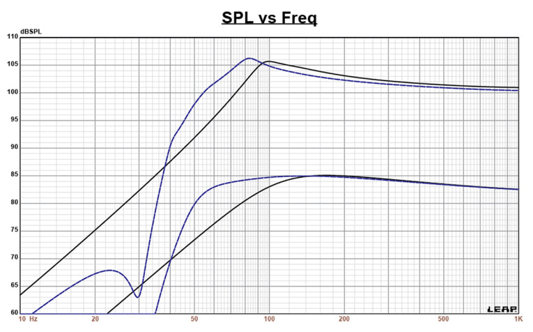
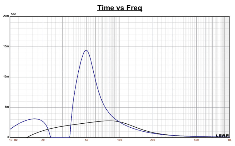
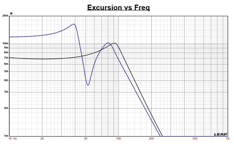
Figure 2 displays the box simulation results for the PTT4.0X woofer in the enclosures at 2.83V and at a voltage level that achieves excursion equal to Xmax + 15% (10.1mm for the PTT4.0X). This resulted in a F3 of 90Hz (-6dB=71Hz) with a Qtc=0.68 for the closed box and a -3dB for the passive radiator simulation of 55Hz (-6dB=49Hz). Increasing the voltage input to the simulations until the Xmax +15% excursion was reached resulted in 105.8dB at 36V for the sealed enclosure simulation and 106dB with a 31V input level for the larger passive radiator box. Figure 3 shows the 2.83V group delay curves and Figure 4 shows the 36V/31V excursion curves.
Klippel analysis for the Purifi Audio 4” woofer was performed this month by Warkwyn with the Klippel KA3 analyzer (Jason Cochrane performed the analysis). As mentioned previously, I will be splitting the Klippel analysis between Redrock Acoustics and Warkwyn. The Bl(X) curve for PTT4.0X seen in Figure 5 is very flat and broad, especially for a 4” driver, but with a small amount of “tilt” and offset. The Bl symmetry curve in Figure 6 shows a small coil-in offset of 1mm offset at 6mm decreasing to about 0.5mm at the 8mm excursion point.
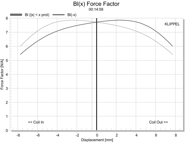
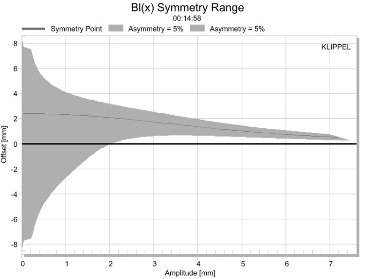
It’s obvious the analyzer didn’t push the driver hard enough to get to the 8.8mm physical Xmax point and beyond. The reason for this is that Jason noted a modicum of mechanical noise at very high excursions and did not want to damage the driver.
For such a small diameter driver, 8.8mm is a lot of excursion. So having motor part noise (suspension and tinsel leads) at such high levels of excursion is not a surprise at all. At the SPL level this implies, I’m willing to say that this noise would be substantially buried in the mix when listening to program material. Either way, Jason discussed this with the folks at Klippel GmbH HQ, and even at that voltage level, the absolute calculated excursion was 9.8mm, which is amazing for this diameter of transducer.
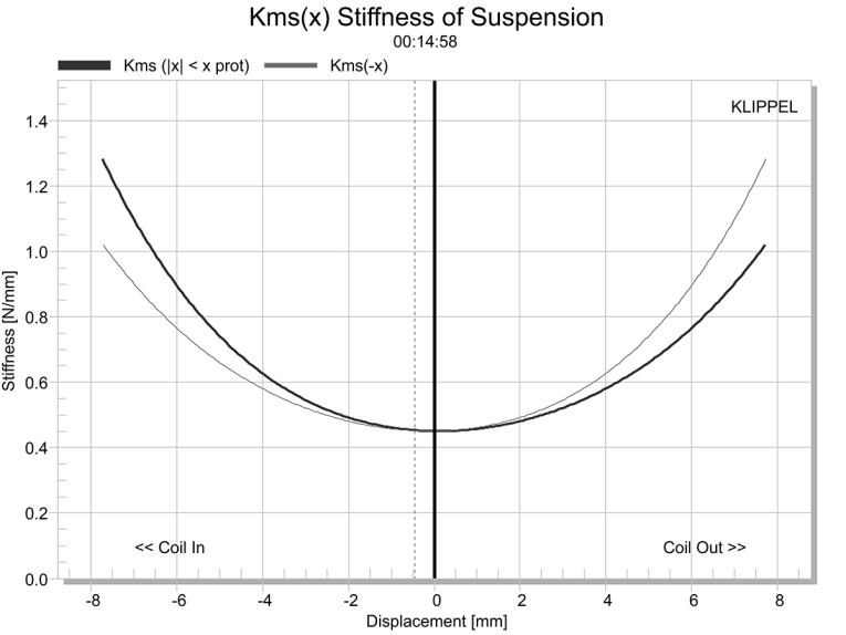
Figure 7 and Figure 8 show the Kms(X) and the Kms symmetry curves. The Kms stiffness of compliance curve seen in Figure 7 is also broad and fairly symmetrical along with a small degree of forward (coil-out) offset and tilt. The Kms symmetry range curve in Figure 8 shows the coil-out offset to settle down to ≤1mm beyond 2mm of excursion. Given that it is the constant, it is likely just a small off-set from magnetic center.
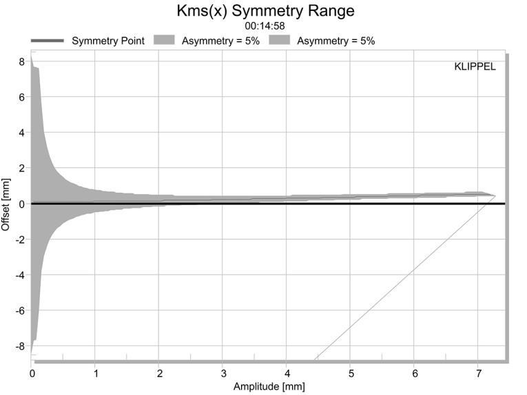
Displacement limiting numbers calculated by the Klippel analyzer using the full-range woofer criteria for Bl was XBl @ 82% (Bl dropping to 82% of its maximum value) equal 9.9mm for the prescribed 10% distortion level. For the compliance, XC @ 75% Cms minimum was only 4.9mm, which means the compliance is the more limiting factor for getting to the 10% distortion level. However, if we use the less conservative 20% distortion criteria, XBl @ 70% greater than 8.6mm and XC @ 50%=7.8mm, showing the Cms number closer to the physical Xmax of the driver.
Figure 9 gives the inductance curve Le(X) for this transducer. Motor inductance will typically increase in the rear direction from the zero rest position as the voice coil covers more of pole in a conventional motor, which is not exactly what you see in this graph and this is anything but a conventional motor. More importantly, the inductive “swing” from maximum inductance to minimum inductance gives a maximum inductive change of only 0.022mH, which is really excellent performance.
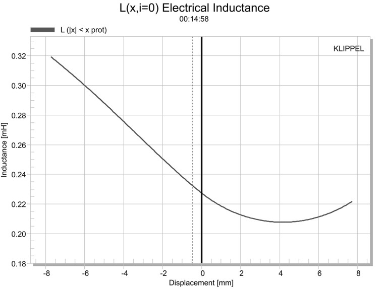
Figure 9: Klippel analyzer L(X) curve for the Purifi Audio PTT4.0X
For the remaining test procedures, I mounted the Purifi Audio PTT4.0X 4” woofer in a foam-filled enclosure that had a 12”×5” baffle and then measured the device under test (DUT) using the LoudSoft FINE R+D analyzer and the GRAS 46BE microphone (courtesy of LoudSoft and GRAS Sound & Vibration) both on- and off-axis from 200Hz to 20kHz at 2.0V/0.5m normalized to 2.83V/1m using the cosine windowed FFT method. All of these SPL measurements also included a 1/6 octave smoothing (this is done to mimic the frequency response resolution I published for years using the LinearX LMS analyzer with 100 point sweeps).
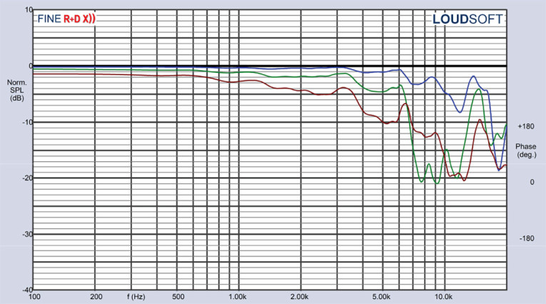
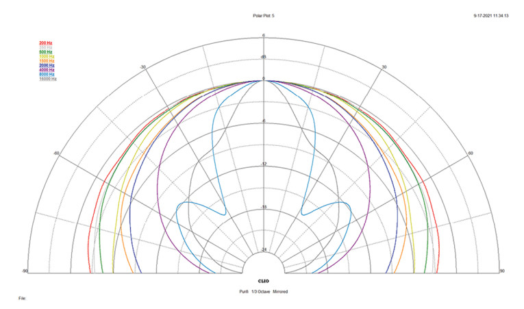
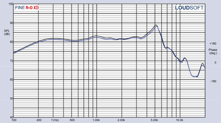
Figure 10 gives the PTT4.0X’s on-axis response, indicating a rather smooth rising response with no break-up modes or peaking out to about 3kHz where the driver begins its low-pass roll-off. Figure 11 displays the on- and off-axis frequency response at 0°, 15°, 30°, and 45°, -3dB at 30° with respect to the on-axis curve occurs at 4.3kHz, so a cross-point in that vicinity or lower should be work well to achieve a good power response and directivity index curve. Figure 12 gives the normalized version of Figure 11. Figure 13 displays the CLIO pocket horizontal polar plot (in 10° increments). And finally, Figure 14 gives the two-sample SPL comparisons for the PTT4.0X, showing a close match (≤0.9dB) throughout the driver’s operating range.
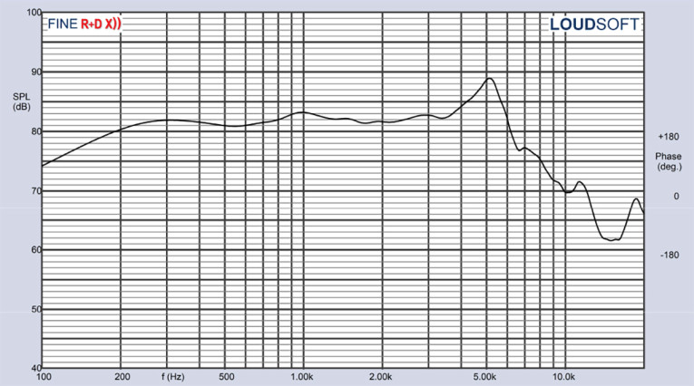
Figure 10: Purifi Audio PTT4.0X on-axis frequency response

For the final group of measurements on the Purifi Audio PTT4.0X, I utilized Listen’s SoundCheck AudioConnect analyzer and SCM microphone (graciously supplied by the folks at Listen, Inc.) to measure distortion and generate time-frequency plots. For the distortion measurement, I rigidly mount the 4” driver in free-air, and set the SPL to 94dB (my criteria for home audio transducers) at 1m (12.4V), using the built-in SoundCheck pink noise stimulus generator and SLM. Then, I measured the distortion with the Listen microphone placed 10cm from the driver. This produced the distortion curves shown in Figure 15, however since the distortion increases rapidly below 100 Hz for this small driver mounted in free air, I reset the scale on the low end from 50Hz to 100Hz, making it much easier to read the distortion about 100Hz, as seen in Figure 16.
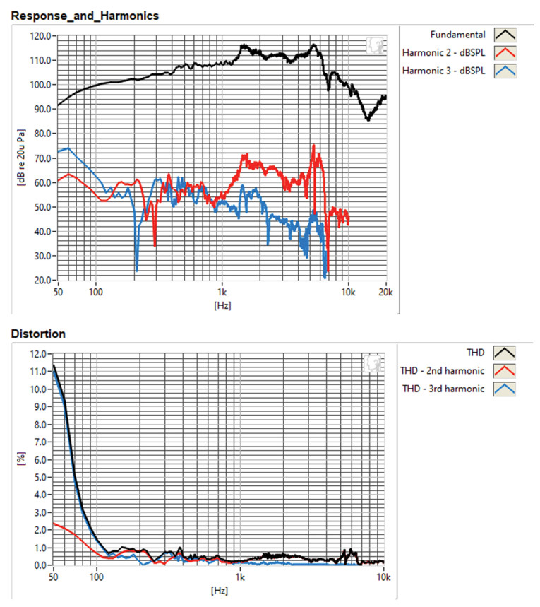

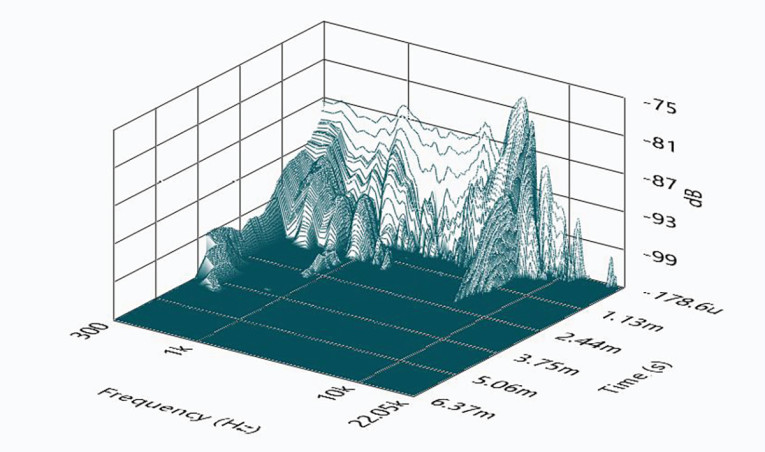
I then engaged the SoundCheck software to get a 2.83V/1m impulse response for this driver and imported the data into Listen’s SoundMap Time/Frequency software. Figure 17 shows the resulting cumulative spectral decay (CSD) “waterfall” plot. Figure 18 shows the Wigner-Ville plot (for its better low-frequency performance).
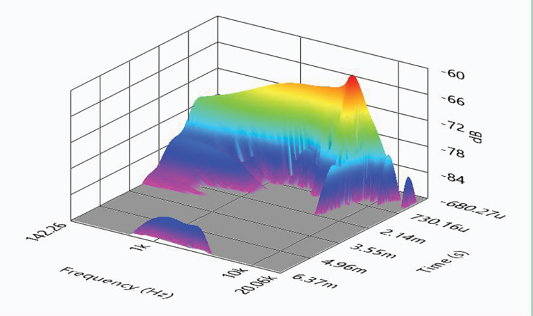
Wigner-Ville plot
Considering the data I collected for the new Purifi Audio PTT4.0X 4” midbass, there is no question that the performance is impressive, not to mention the various engineering innovations. Used in a compact two-way application in conjunction with a passive radiator, the performance is outstanding for a 4” transducer. I think it would also be a good choice for a compact, sealed box home theater LCR/surround speaker.
The company’s background is impressive, and Purifi Audio has been getting a lot of attention since its first announcement in early 2019. Readers can learn more about this interesting Danish loudspeaker and amplifier company in three articles published in audioXpress: “Purifi Audio Promises to Reduce Distortion in Speakers and Amplifiers” (April 18, 2019 by J. Martins); “Purifi Audio: A Conversation About Amplifiers and Speakers” (June 6, 2019 by J. Martins); and “Purifi Audio - A Straight Wire to the Soul of Music” (October 23, 2019 by Jan Didden). Also, in Voice Coil, Purifi Audio’s 6.5” PTT6.5X extremely low magnetic distortion midbass woofer was featured in the July 2021 Test Bench column.
For a new company, Purifi Audio has unleashed an impressive overall group of transducer designs and combined this with a high level of build quality. The PTT4.0X is a well-crafted product, specifically intended for the high-end two-channel hi-fi, home theater, or studio monitor markets.
As always, the only thing I regret about these Test Bench reports is that I do not have the time to design these drivers into a system and do a subjective evaluation. For more information, visit www.purifi-audio.com. VC
This article was originally published in Voice Coil, November 2021.