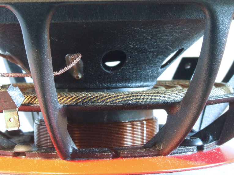
For this month’s Test Bench explication, I requested the PTT6.5X04-NFA-01 midbass driver. The PTT6.5’s feature set begins with a proprietary eight-spoke cast-aluminum frame, comprised of narrow (about 3mm to 1.5mm) tapered spokes, completely open below the spider (damper) mounting shelf for cooling. Additional cooling for this driver is provided by six oval-shaped 12mm × 8mm vents in the cone beneath the dust cap, with no pole vent.
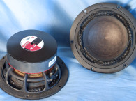
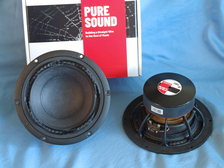
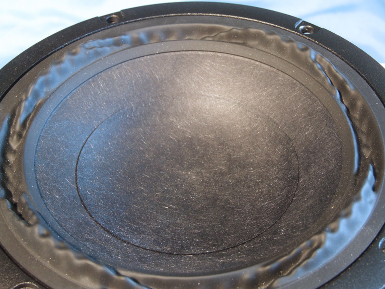
The cone assembly consists of a mildly curvilinear paper cone made with a proprietary fiber mix, a 3.13” concave dust cap, plus the addition of a V-shaped edge reinforcing ring glued around the outside rim of the back side of the cone (Photo 1 and Photo 2). This reinforcing ring makes the cone edge extremely stiff, and would appear to severely dampen cone edge resonances.
Compliance is provided by NBR surround, which is an entire story in itself. Looking at Photo 1 and Photo 3, this is probably the most unique surround in the history of Voice Coil’s Test Bench. Surrounds, besides providing compliance and centering, are indeed a source of noise and distortion as well as a tool for damping the outside rim of a cone.
It is not a surprise that surrounds have been the subject of numerous patents that offer solutions based on shape, material, and complex material thickness, but I have yet to see anything this extreme. The PTT6.5’s configuration is a combination of alternating sections of both reverse roll and positive roll, plus some interesting articulation within the alternating sections. Note that the positive roll has an obvious left/right asymmetry articulation, which yields a positive/negative going articulation on either end of the reverser roll sections.

I corresponded with Lars Risbo regarding the technology in the PTT6.5X. Here is what he had to say about the surround: “The surround’s geometry serves multiple purposes: the strange shape ensures that its radiating area Sd is kept constant over its full stroke (eliminating a strong IMD source). It further tames the usual cone edge break-up (together with the stiffening ring below the cone edge) and is very resilient to the back pressure from a small box. Finally, it is excellent at keeping the coil centered even at large excursions. The combined result is that the IMD hovers around the theoretical Doppler limit.”
I commented that the amount of FEA time must have been substantial, which Risbo confirmed: “Yes, lots of FEA CPU time went into the design, both the motor system as well as the moving parts. We use a combo of COMSOL and Matlab to perform the geometry optimization. Together COMSOL is doing the FEA and Matlab is doing more math support and controlling the optimization process. This is an area where we are continuously stepping up and computational requirements seem to go exponential (always need more and faster machines). We will apply shape optimization to more and more corners of the design.”
Remaining compliance is provided by a 3.5” diameter symmetrical roll flat spider (damper). The motor consists an FEA-optimized 100mm × 25mm ferrite ring magnet type with milled plates, the front plate having a red coating and the backplate a black emissive coating, plus a neodymium pole magnet that serves to linearize the Bl. Driving the cone assembly is a 39mm (1.54”) diameter four-layer voice coil wound with round copper-clad aluminum wire (CCAW) on a non-conducting fiberglass former. Like the surround, this four-layer coil also exhibits some very unique engineering. Unlike a winding that has the same width across its full length, this four-layer coil as it has alternating two- and four-layer sections on the length of the coil with varying widths of two- and four-layer sections as seen in Photo 4.
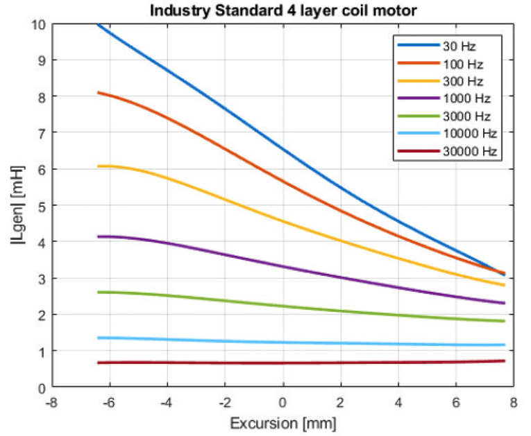
Figure 1 and Figure 2 show the comparison of the inductance variation with frequency of a standard four-layer coil and the Purifi four-layer coil. I suspect this concept came from the Audio Engineering Society (AES) research paper presented by Morten Halvorsen, Carsten Tinggaard (both members of the Purifi team), and Finn T. Agerkvist, titled “Flux Modulation in the Electrodynamic Loudspeaker” (presented at the 138th AES Convention, May 6, 2015, paper #9317).
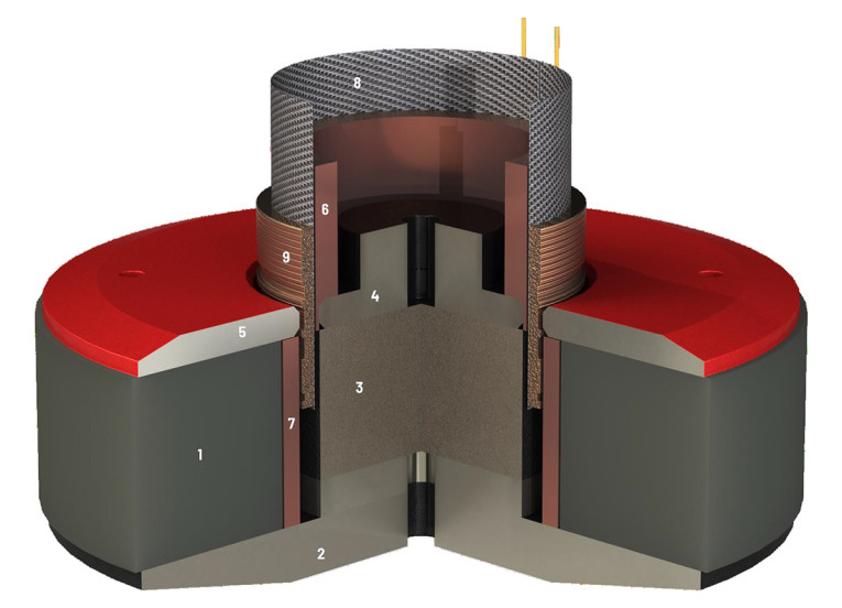
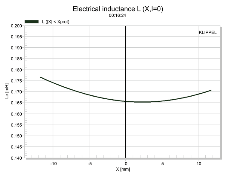
This effectiveness of an articulated coil winding at reducing dynamic inductance will also show in the Klippel L(X) curve to be discussed later. Here is what Risbo said about the motor design: “The most interesting (and expensive) parts of the motor system are not visible from the outside. [Photo 4 shows] a yet unpublished cross section rendering (although I have shown the parts in a YouTube interview so it is public info by now)."
“Most of the pole (3) is replaced by a strong neodymium magnet: This reduces the coil inductance significantly as well as the inductance vs position gradient all the way to DC (this cannot be achieved by shorting rings since they only work above a certain frequency determined by the their cross sectional area). An iron pole piece extension (hat) (4) is optimized to flatten the inductance vs position further. This virtually eliminates the current dependency of the Bl factor (as we have shown in our AES paper from 2016) as well as the position dependency of the coil impedance — two major nonlinear sources of especially IMD (changing the Bl or coil impedance modulates the sensitivity of the speaker leading to amplitude modulation)."
“Two very thick copper shorting rings (6) and (7) are surrounding the coil within its full linear stroke. The purpose of these is to further lower the inductance and shield the iron from the AC field of the coil. Such AC field in the iron is a major source of distortion (hysteresis and BH saturation). Note that the top ring (6) extends through the gap since the AC field induced in the iron concentrates at surfaces close to the coil and thus needs the most shielding."
“The pole ventilation is through holes in the membrane to get enough venting area to eliminate air rushing noises.” Also noteworthy is the 250W IEC 268-5 power handling rating, which is impressive for a 6.5” transducer. Last, the voice coil copper braid lead wires are terminated to gold-plated solderable terminals located on one side of the frame.

I used the LinearX LMS analyzer and the Physical LAB IMP Box (the same type of fixture as a LinearX VIBox) to create both voltage and admittance (current) curves with the driver clamped to a rigid test fixture in free-air at 0.3V, 1V, 3V, 6V, 10V, and 15V with oscillator on time between sweeps to simulate the actual thermal process over time. The 15V curves were too nonlinear to get a sufficient curve fit and were discarded. Following my protocol, I no longer use a single added mass measurement and instead use the company-supplied Mmd data (11.85 grams for the PTT6.5X).
The collected data, in this case the ten 550-point (0.3V-10V) sine wave sweeps for each Purifi sample, were post-processed and the voltage curves divided by the current curves to generate impedance curves, with the phase derived using the LMS calculation method. I imported the data, along with the accompanying voltage curves, to the LEAP 5 Enclosure Shop software.
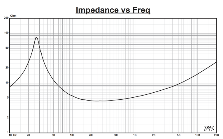
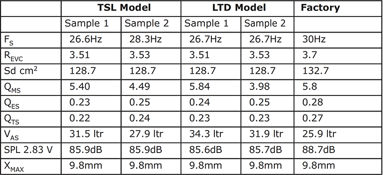
Figure 3 shows the 1V free-air impedance curve. I selected the 1V TSL data in the transducer parameter derivation menu in LEAP 5 and created the parameters for the computer box simulations. Table 1 compares the LEAP 5 LTD/TSL TSP data and factory parameters for both of the Purifi PTT6.5X04-NFA-01B samples.
LEAP LTD and TSL parameter calculation results for the Purifi PTT6.5X appear to correlate reasonably well with the factory published data. I set up the computer enclosure simulations using the LEAP LTD parameters for Sample 1. Two simulated enclosures were programmed into the LEAP 5 software — one Butterworth Qtc = 0.7 sealed box with 0.14 ft3 air volume with 50% damping material (fiberglass); and a vented modified Quasi Third-Order Butterworth (QB3) alignment with a 0.25 ft3 volume with 15% damping material tuned to 26Hz. Note that while this works in simulation, for this low of a tuning in a relatively small box, a passive radiator would likely be more appropriate.
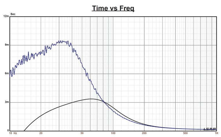
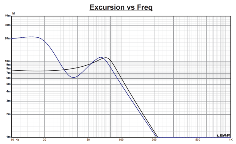
Figure 4 displays the box simulation results for the PTT6.5X woofer in the sealed and vented enclosures at 2.83V and at a voltage level that achieves excursion equal to Xmax + 15% (11.3mm for the PTT6.5X). This resulted in a F3 of 75Hz (-6dB =58Hz) with a Qtc = 0.68 for the closed box and a - 3dB for the vented simulation of 52Hz (-6dB = 41Hz). Increasing the voltage input to the simulations until the Xmax +15% excursion was reached resulted in 110dB at 41V for the sealed enclosure simulation and 110.5dB with a 39V input level for the larger vented box. Figure 5 shows the 2.83V group delay curves. Figure 6 shows the 15V/16V excursion curves.
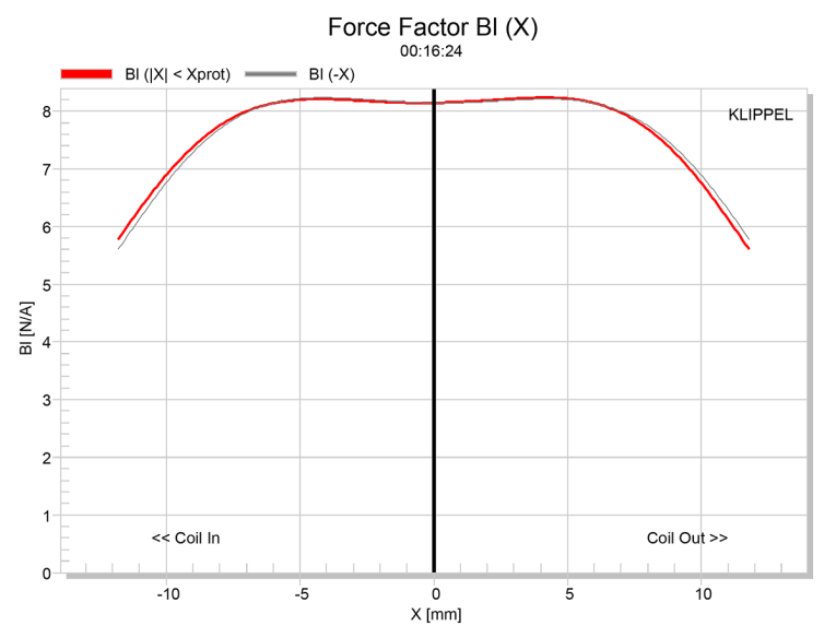
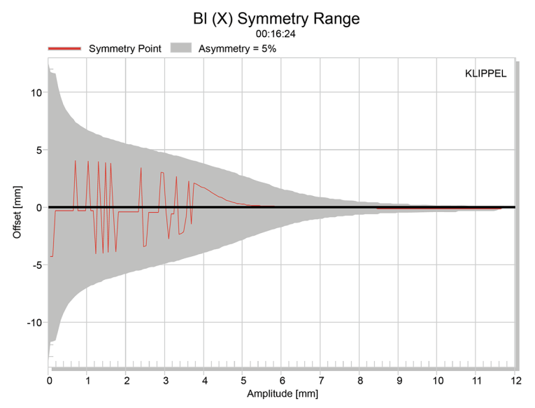
Klippel analysis for the Purifi PTT6.5X woofer was performed this month by Warkwyn (Jason Cochrane performed the analysis) with the Klippel KA3 analyzer. The Bl(X) curve for PTT6.5X (Figure 7) is very flat and broad, especially for a 6.5” driver, but with a total lack of “tilt” and nearly zero offset. The Bl symmetry curve shown in Figure 8 reveals zero offset once the graph reached a place of certainty from about 5mm to over 11mm. Note that the analyzer had some unusual behavior from 1mm to 4mm skewing up and down repeatedly. Jason Cochrane and I discussed this, and suspected this behavior was due to the shifting two- to four-layer nature of the Purifi voice coil.
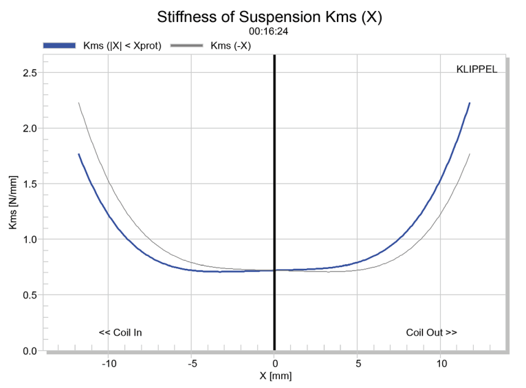
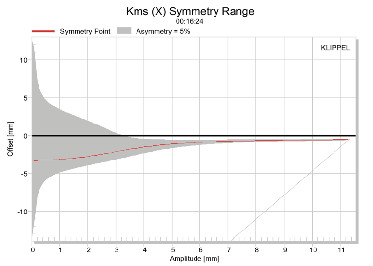
Figure 9 and Figure 10 show the Kms(X) and Kms symmetry curves for the PTT6.5X driver. The Kms stiffness of compliance curve seen in Figure 9 is also broad and symmetrical and with a small degree of rearward (coil-in) offset. The Kms symmetry range curve in Figure 10 shows the coil-in offset to settle down to ≤ 1mm beyond 5mm of excursion.
Displacement limiting numbers calculated by the Klippel analyzer using the full-range woofer criteria for Bl was XBl @ 82% (Bl dropping to 82% of its maximum value) equal to 10.2mm for the prescribed 10% distortion level. For the compliance, XC @ 75% Cms minimum was only 7.2mm, which means that for the Purifi PTT6.5X woofer, the compliance is the more limiting factor for getting to the 10% distortion level. However, if we use the less conservative 20% distortion criteria, XBl @ 70% = 11.7mm and XC @ 50% = 9.7mm, showing the Cms number closer to the driver’s physical Xmax.
Figure 11 gives the inductance curve Le(X). Motor inductance will typically increase in the rear direction from the zero rest position as the voice coil covers more of the pole in a conventional motor, which is not exactly what you see in this graph. More important, the inductive “swing” from maximum inductance to minimum inductance from 10mm coil-in to 10mm coil-out gives a maximum inductive change of an almost nonexistent 0.009mH, which is nothing short of amazing and it is the lowest recorded inductive swing since Voice Coil started using the Klippel analyzer. Cheers to Purifi!
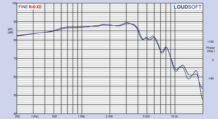
For the remaining test procedures, I mounted the Purifi PTT6.5X woofer in a foam-filled enclosure that had a 17” × 8” baffle. Then, I measured the DUT using the LoudSoft FINE R+D analyzer and the GRAS 46BE microphone (courtesy of LoudSoft and GRAS Sound & Vibration) both on- and off-axis from 200Hz to 20kHz at 2.0V/0.5m, normalized to 2.83V/1m, using the cosine windowed Fast Fourier Transform (FFT) method. All of these SPL measurements also included a 1/6 octave smoothing.
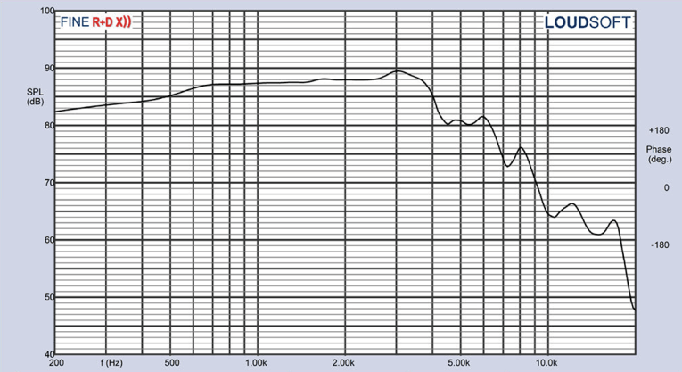
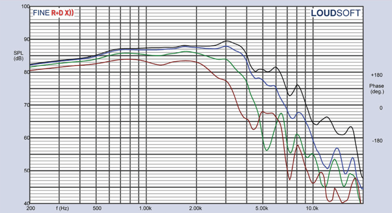
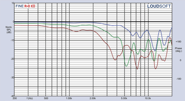
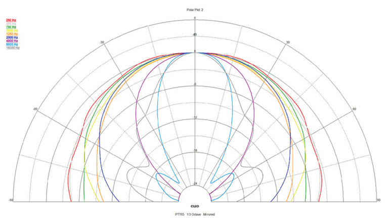
Figure 12 gives the Purifi PTT6.5X’s on-axis response, indicating a rather smooth rising response with no breakup modes or peaking out to about 3kHz, where the driver begins its low-pass roll-off. Figure 13 displays the on- and off-axis frequency response at 0°, 15°, 30°, and 45°, -3dB at 30° with respect to the on-axis curve occurs at 2.2kHz, so a cross point in that vicinity or lower should work well to achieve a good power response. Figure 14 gives the normalized version of Figure 13. Figure 15 displays the CLIO pocket horizontal polar plot (in 10° increments). And finally, Figure 16 gives the two-sample SPL comparisons for the PTT6.5X, showing a close match (≤ 0.7dB) throughout the driver’s operating range.
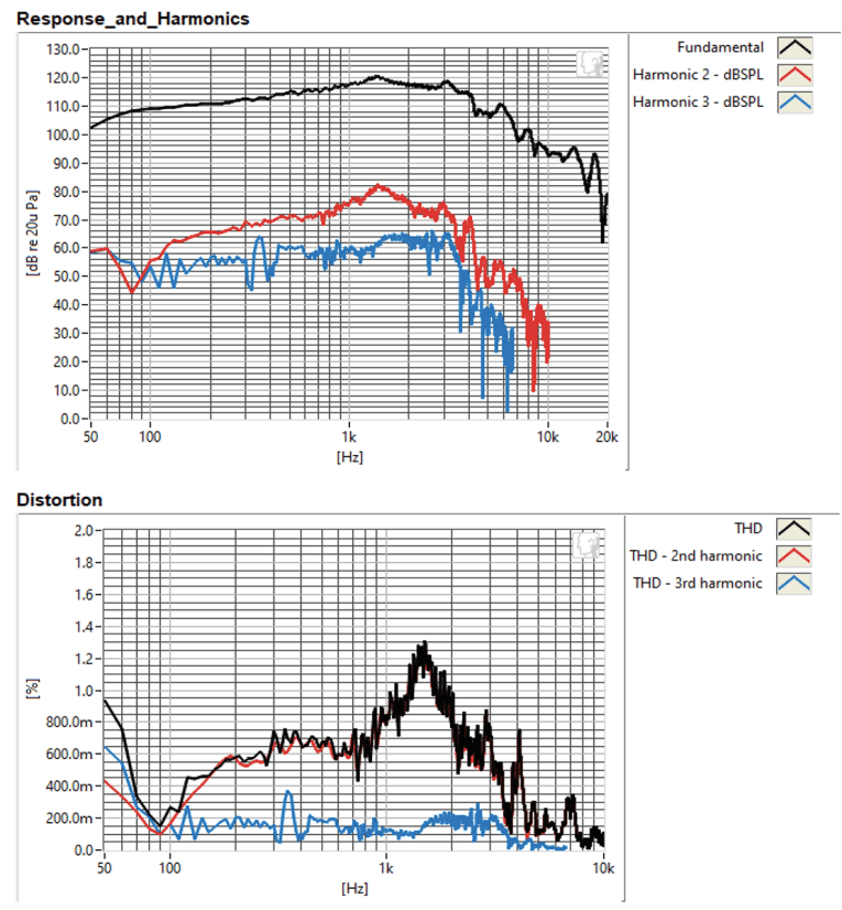

For the remaining series of tests on the Purifi PTT6.5X, I employed Listen’s SoundCheck AudioConnect analyzer and SCM microphone (supplied to us by Listen, Inc.) to measure distortion and generate time-frequency plots. For the distortion measurement, I mounted the Purifi PTT6.5X rigidly in free-air, and set the SPL to 94dB (my criteria for home audio transducers) at 1m (7.25V) using a SoundCheck pink noise stimulus. Next, I measured the distortion with the microphone placed 10cm from the driver. This produced the distortion curves shown in Figure 17, which is distinguished by very low third-harmonic content throughout the operating range of this transducer, and low second- and third-harmonic distortion between 50Hz to 100Hz.
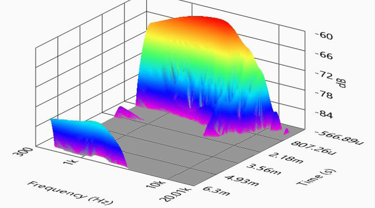
I then engaged the SoundCheck software to get a 2.83V/1m impulse response and imported the data into Listen’s SoundMap Time/Frequency software. Figure 18 shows the resulting Cumulative Spectral Decay (CSD) waterfall plot. Figure 19 shows the Wigner-Ville plot (for its better low-frequency performance).
Looking at all the various data I collected for the new Purifi PTT6.5X midbass, the performance and the various engineering innovations are impressive. For a new company, Purifi Audio has fielded an impressive overall design and combined with a high level of build quality, this is a well-crafted product specifically intended for the high-end hi-fi or studio monitor market. For more information, visit www.purifi-audio.com. VC
This article was published in Voice Coil July 2021.