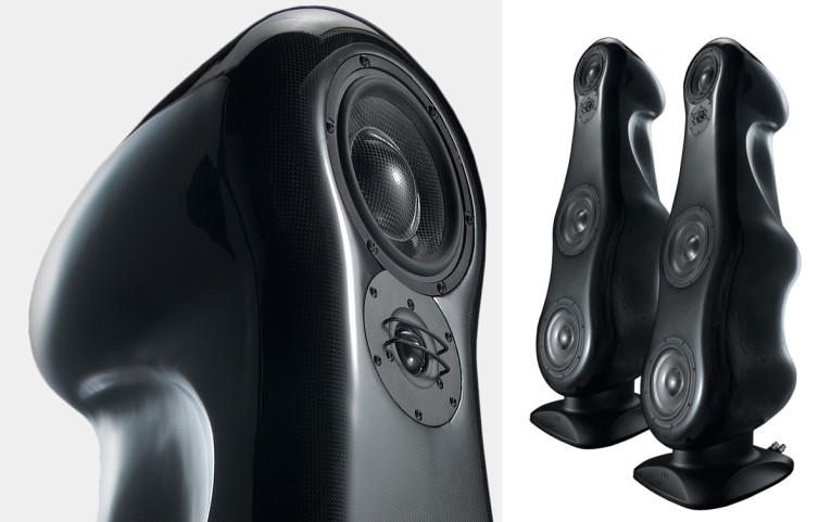
Unlike conventional loudspeakers, it has absolutely no internal damping: the inside of the cabinet is empty. The enclosure is allowed to vibrate in a controlled manner along with the drive units and uses this energy as part of the reproduced sound. The clever part is that the cabinet “sings” with the drive unit but stops immediately when the drive unit stops so there are no delayed resonances. According to Morel, the result is a speaker that sounds as though it has no cabinet at all.
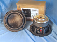
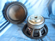
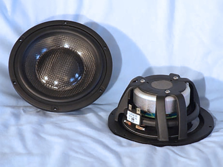
Similar to the cabinet utilized in the fat lady speaker, the Morel SCW 636 uses a three-layer composite cone and dust cap that combines carbon fiber/Rohacell/carbon fiber that is both light weight and very stiff. The remainder of the cone assembly includes a NBR surround, cloth spider, and a 3″ diameter voice coil using an aluminum former wound with aluminum Hexatech wire (Hexatech wire is multi-sided voice coil wire that provides a higher density winding than standard round wire). The complete assembly is loaded into a propriety diecast aluminum frame that has minimum reflective surfaces trademarked by Morel as “Uniflow.”
The motor structure uses the Morel hybrid technology that combines a ferrite ring magnet with a neodymium slug type magnet. This also includes a distortion reducing Faraday shield (shorting ring) in the form of a copper cap on the pole piece. The voice coil lead wires are terminated to a pair of gold-plated terminals.
I began testing the SCW 636 using the LinearX LMS analyzer and VIBox to produce both voltage and admittance (current) curves with the driver clamped to a rigid test fixture in free-air at 0.3V, 1V, 3V, 6V, and 10V. I discarded both 10V curves because the software was not about to get a good curve fit and the driver was too nonlinear at that voltage level. Next, I post-processed the remaining eight 550 point stepped sine wave sweeps for each sample and divided the voltage curves by the current curves (admittance) to produce impedance curves, phase added using LMS calculation method, and along with the accompanying voltage curves, loaded into the LEAP 5 Enclosure Shop software.
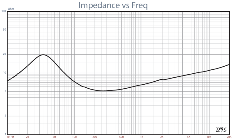
Besides the LEAP 5 LTD model results, I also generated a LEAP 4 TSL model set of parameters using just the 1V free-air curves. I selected the final data, which includes the multiple voltage impedance curves for the LTD model (see Fig. 1 for the 1V free-air impedance curve) and the 1V impedance curve for the TSL model, and produced the parameters in order to perform the computer box simulations.
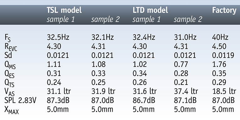
Table 1 compares the LEAP 5 LTD and TSL data and factory parameters for both SCW 636 samples. Looking at the data in Table 1, the F0/Qt ratios between the measured data and the factory data are reasonably close, although you do see a variance between the Vas numbers. However, following my standard “Test Bench” protocol, I produced two computer enclosure simulations using the LEAP LTD parameters for Sample 1. I produced two box simulations, one sealed and one vented. For the closed box simulation I used a 0.16ft3 enclosure with 50% fiberglass fill material, and for the vented box, a 0.23ft3 QB3 type vented alignment with 15% fiberglass fill material and tuned to 47.6Hz.
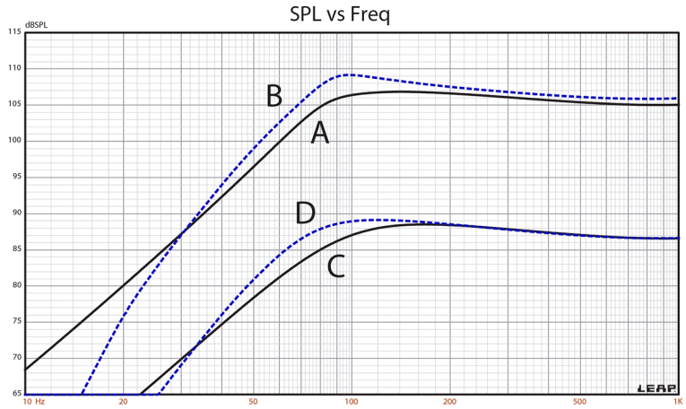
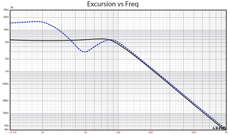
Figure 2 illustrates the results for the SCW 636 in the sealed and vented boxes at 2.83V and at a voltage level high enough to increase cone excursion to Xmax + 15% (5.75mm). This yielded a F3 = 83Hz with a box/driver Qtc of 0.73 for the 0.16ft3 sealed enclosure and –3dB = 67.5Hz for the 0.23ft3 vented simulation. Increasing the voltage input to the simulations until the maximum linear cone excursion was reached resulted in 107dB at 26.5V for the sealed enclosure simulation and 109dB with a 30V input level for the larger vented box (see Figs. 3 and 4 for the 2.83V group delay curves and the 26.5/30V excursion curves).
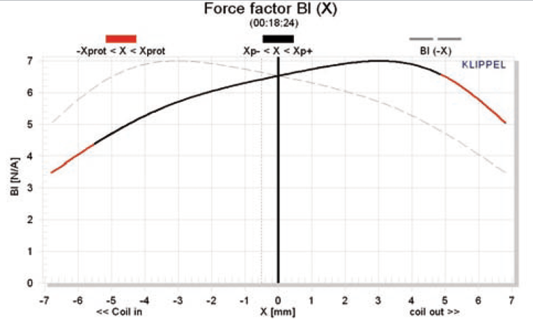
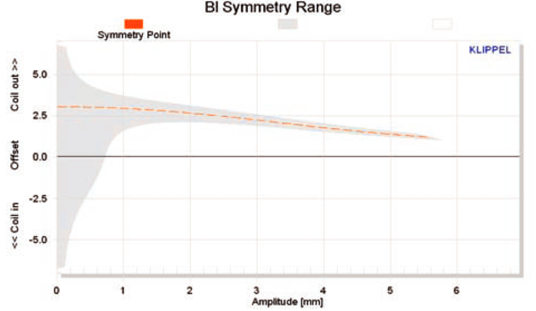
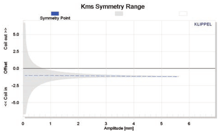
Looking at the Kms Symmetry Range curve, you see a constant 1.4mm rearward (coil-in) throughout the operating range of the driver. This suggests a physical offset that is slightly off magnetic zero in the gap area. This will generally produce 2nd-order harmonic distortion, which for the most part is judged as being pleasant and desirable. Note that while these offsets are distortion producing, it does not indicate that this necessarily degrades the sound quality of the driver. Morel, like most of the high-end home and car audio manufacturers, does a substantial amount of listening in the development of any driver, and because this looks like a deliberate displacement, I conclude that while on the surface the Klippel data looks rather out of balance, the SCW 636 is probably a very good-sounding driver.
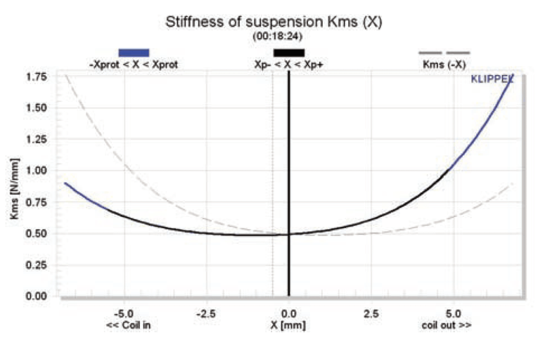
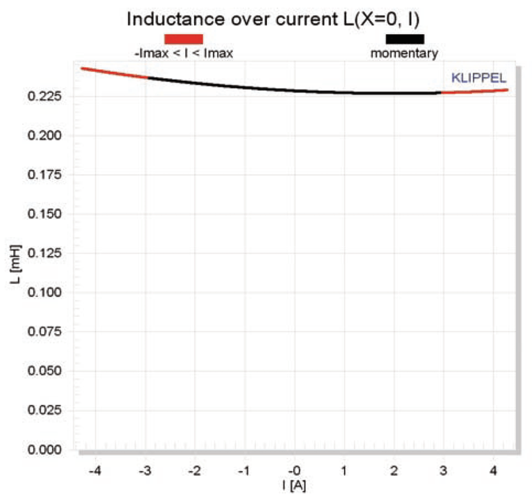
Displacement limiting numbers calculated by the Klippel analyzer for the SCW 636 were XBl at 82% Bl = 3.8mm and for XC at 75% Cms was 2.9mm, which means that for the Morel carbon fiber cone woofer, the compliance is the limiting factor for the 10% prescribed distortion level. Figure 9 gives the inductance curves L(X) for the SCW 636. Because the SCW 636 incorporates a copper shorting sleeve in the motor system, the result is an extremely minor change in inductance throughout the driver’s operating range (0.08mH from Xmax in to Xmax out), a key to low distortion performance (in this case undesirable 3rd-order harmonic distortion).
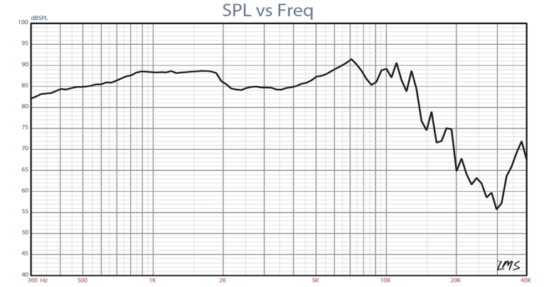
Following the Klippel testing, I mounted the Morel 6″ woofer in an enclosure which had a 17″ × 8″ baffle and was filled with damping material (foam) and then measured the DUT on- and off-axis from 300Hz to 40kHz frequency response at 2.83V/1m using a 100-point gated sine wave sweep. Figure 10 gives the SCW 636’s on-axis response displaying a very smooth rising response to about 1.8kHz, followed by a 4dB drop in SPL leading to a smooth rise to a break-up mode at 7kHz, followed by the low-pass rolloff.
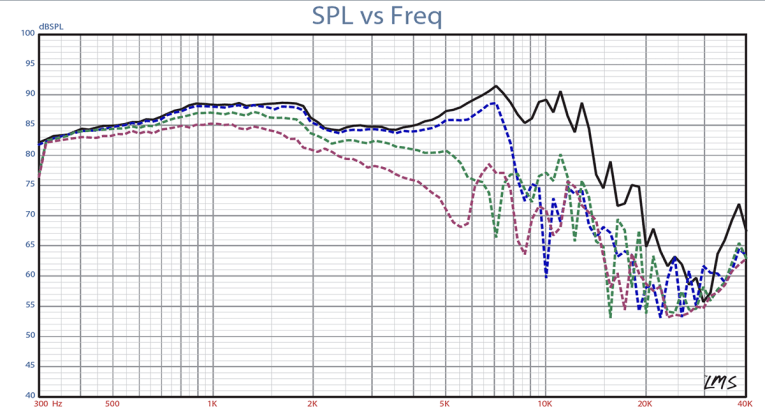
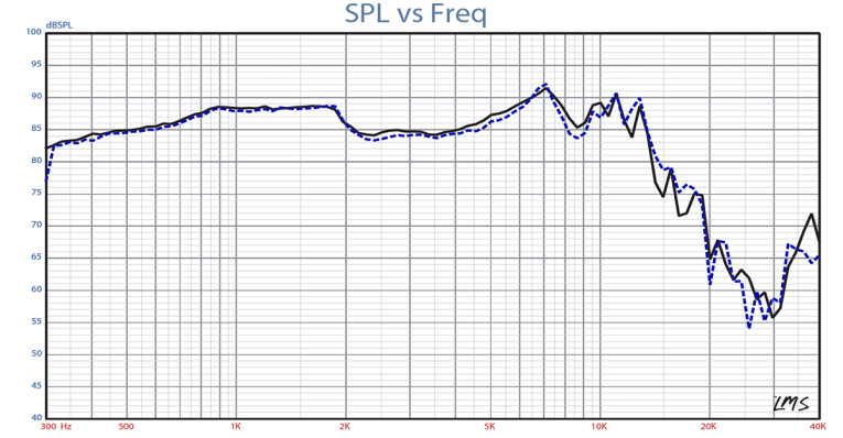
Figure 11 has the on- and off-axis frequency response at 0, 15, 30, and 45°. -3dB at 30° with respect to the on-axis curve occurs at 3.6kHz, higher than most 6″ drivers, so a crossover somewhat above the usual 3kHz crossover frequency should be appropriate. The last SPL measurement is shown in Fig. 12 and gives the two-sample SPL comparisons for the 6.0″ Morel driver, showing a close match throughout the operating range.
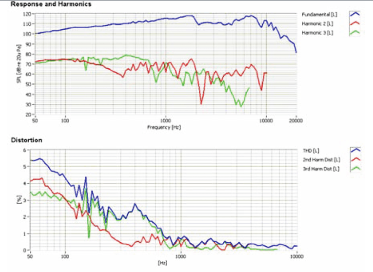
For the last group of tests, I employed the Listen Inc. SoundCheck analyzer (courtesy of Listen Inc.) to measure distortion and generate time frequency plots. Setting up for the distortion measurement consisted of mounting the woofer rigidly in free-air, and the SPL set to 94dB at 1m using a noise stimulus (SoundCheck has a software generator and SPL meter as two of its utilities), and then the distortion measured with the Listen Inc. microphone placed 10cm from the dust cap. This produced the distortion curves shown in Fig. 13.
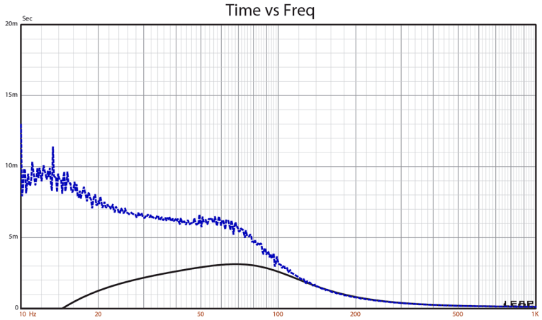
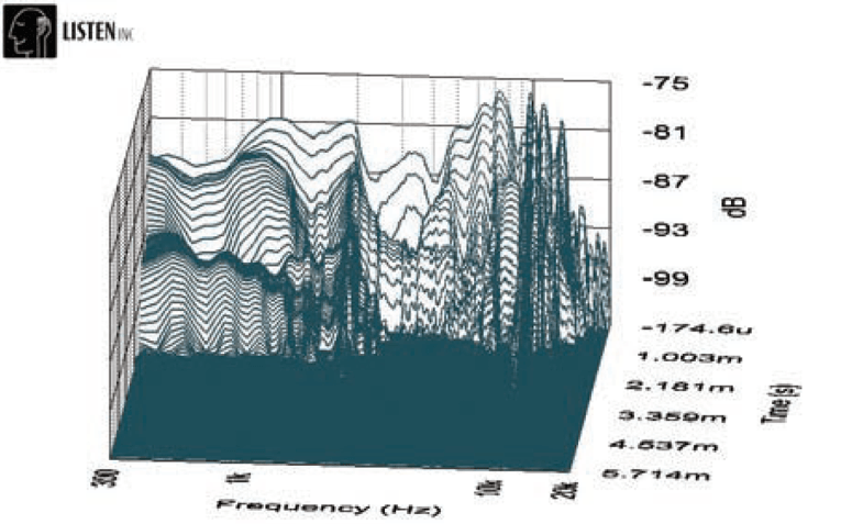
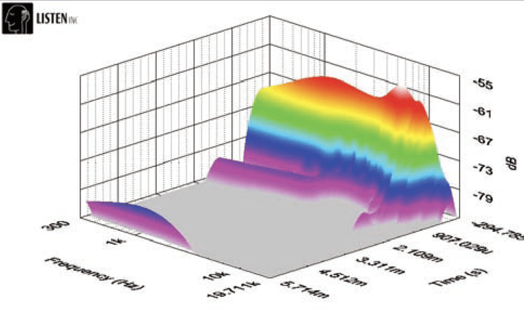
Last, I employed the SoundCheck analyzer to get a 2.83V/1m impulse response for this driver and imported the data into Listen Inc.’s SoundMap Time/Frequency software. The resulting CSD waterfall plot is given in Fig. 14 and the Wigner-Ville logarithmic surface map (for its better low-frequency performance) plot in Fig. 15. I designed many systems over the years using Morel products, and I am certainly a “fan.” The SCW 636 looks like another interesting driver from Morel and worth considering. For more information on these and the other new Morel drivers, visit www.morelhifi.com VC
This article was originally published in Voice Coil, May 2010.