Rotary Transducer with Improved High-Frequency Output
Patent Number: 9,363,611
Inventor: F. Bruce Thigpen; (Tallahassee, FL)
Assignee: F. Bruce Thigpen; (Tallahassee, FL)
Filed: October 16, 2014
Current CPC Class: H04R 1/10 (20060101)
Granted: June 7, 2016
Number of Claims: 20
Number of Drawings: 18
Abstract from Patent
A rotary sound transducer having an improved output at higher frequencies. The invention includes stiff vanes that are preferably rigidly attached to a hub. A torsional actuator is provided in each vane. The torsional actuator selectively twists the tip portion of each vane. The torsional actuator for each vane is activated by an input energy source corresponding to the sound waves that are desired. The input force may also be electromechanical energy, purely mechanical energy, or some other form of energy.
Independent Claims
1. A method for transforming cyclical input energy into sound, comprising: a. providing a hub; b. providing a plurality of vanes, each vane including, i. a hub interface connected to said hub, ii. a root extending outward from said hub interface, iii. a middle region extending outward from said root, iv. a variable pitch region extending outward from said middle region, v. a torsional actuator configured to twist said variable pitch region, said torsional actuator including a torque input interface proximate said hub interface; c. providing a mechanical transducer configured to transmit said cyclical input energy to torque applied at said torque input interface on said vanes; d. rotating said hub, thereby rotating said plurality of vanes; and e. while said hub is rotating, applying said cyclical input energy to said mechanical transducer, thereby cyclically twisting said vanes and producing sound.
8. A method for creating sound, comprising: a. providing a plurality of vanes arrayed around a central axis of rotation, each vane including, i. a hub interface proximate said central axis of rotation, ii. a root extending outward from said hub interface, iii. a middle region extending outward from said root, iv. a variable pitch region extending outward from said middle region, v. a torsional actuator configured to twist said variable pitch region, said torsional actuator including a torque input interface proximate said hub interface; b. rotating said vanes about said central axis of rotation; and c. while said vanes are rotating, cyclically applying torque to said torque input interface on each of said vanes, thereby cyclically twisting said vanes and creating said sound.
15. A method for creating sound, comprising: a. providing a plurality of vanes connected to a hub, each vane including, i. a hub interface rigidly connected to said hub, ii. a root extending outward from said hub interface, iii. a middle region extending outward from said root, iv. a variable pitch region extending outward from said middle region, v. a torsional actuator passing through said vane from said hub interface to said variable pitch region, said torsional actuator being configured to twist said variable pitch region and including a torque input interface proximate said hub interface; b. rotating said hub thereby rotating said vanes; and c. while said vanes are rotating, cyclically applying torque to said torque input interface on each of said vanes, thereby cyclically twisting said vanes and creating said sound.
Reviewer Comments
In the realm of low-frequency reproduction, the key to success is cubic volume displacement. For each decreasing octave in frequency, the transducer area/excursion requirement goes up 12dB for a given sound pressure level (SPL). Direct radiating loudspeaker transducers tend to exhibit a poor acoustic impedance match and are inefficient at low frequencies. This can be overcome to a certain degree by re-matching the transducer and “magnifying” its acoustic output with a larger waveguide or a horn. Unfortunately, the scaling factor for these acoustic enhancers (or most any conventional enclosure type) requires an increase in size of approximately eight times for each halving of frequency to maintain a given efficiency.
Many modern movies contain audio content in the range of 2 to 20 Hz, at substantial levels. Just a few of the many examples of movies including passages with 5Hz content are Finding Nemo, Pan’s Labyrinth, Spiderman 2, Black Hawk Down, Final Destination 2, and Gladiator. Even with some of the best commercially available subwoofers and leveraging the available room gain, reproduction of 5 Hz fundamentals with low distortion at reference level is unlikely. With cubic volume of air movement being paramount to reproduce high-level, sub-20 Hz program material, one is incentivized to look for other options to produce infrasonic output.
In general, if anyone wants to move a lot of air at DC/0 Hz on a hot summer’s day, they don’t hook up a loudspeaker, they buy a fan! Some of the earliest work in the US utilizing a fan to move air at an audio rate was accomplished by the innovative and prolific Thomas Danley, as disclosed in US 5,140,641 “Servo Valve Loudspeaker.” This version of a fan-based system used a motor powered fan operating with fixed blades in single polarity, sending air down a tunnel to a servo driven, rotating vane to modulate the air flow at the audio rate while directing the air flow in two alternating directions and regulating the amplitude of the airflow to set amplitude. This system was used for sonic boom simulation and was capable of 132dB at 2m from 30Hz down to 3Hz.
Just over 10 years later, Bruce Thigpen developed and commercialized a new type of integrated fan-based loudspeaker and filed for a patent application on the device (US patent application number 10/442,852, which was never granted, due to almost identical prior art from Japan in 1983; JP58-151,200, “Ultra Low Sound Loudspeaker” by Okamura Shirou, and the granddaddy of fan-based woofer systems, patented in 1942, US2,304,022, “Sound Reproducing Device” by Royden C. Sanders at RCA.)
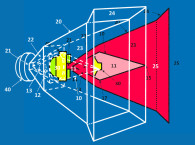
The primary components of Thigpen’s original system are shown in the Figure 1 drawing, which incorporates a “swash plate” (36) to vary the pitch of the rotating vanes (34) in a manner substantially the same as the mechanism used to vary the pitch of a helicopter’s main rotor blades. While the actual device uses four or five vanes, for illustration purposes, the device shown in Figure 1 utilizes a pair of vanes driven in the arc shown by shaft 30. A motor within housing 26 spins shaft 30. Swash plate 36 actuates two linkages 40 connected to a pitch-actuating mechanism on each vane. The reader will observe that moving the linkages will cause the deflection of the two vanes 34 so that the angle of attack of each vane (relative to the air flowing over its leading edge) is increased or decreased. The angle of attack of the two vanes is changed in unison.
Swash plate 36 translates in a direction that is parallel to the central axis of shaft 30. The swash plate is urged toward the vanes or away from the vanes by the motion of voice coil 20. Voice coil 20 is an electromagnetic device such as used in a common woofer transducer. The voice coil is suspended in a neutral position by suspension spider 22 or held in a neutral position by the influence of the air load on the leading and trailing edges of the vanes. Wire bundle 42 includes the wires used to provide electrical power to the motor that rotates the vanes at a constant rate and other wires used to provide the audio input signal controlling the motion of the voice coil.
Conventional rotary bearings support the rotating shaft and the bearing assembly is a thrust-type bearing. It enables swash plate 36 to rotate with respect to voice coil 20 while also transmitting a linear force. Although the mechanism shown is reminiscent of that used in a helicopter’s main rotor, the reader will note that the pitch of the two vanes is not varied independently but are always locked in unison. Thus, using helicopter terminology, the simple swash plate is able to vary the “collective” pitch but is unable to create cyclical variations customarily produced by tilting the swash plate in a helicopter.
The shaft rotates the assembly at a speed which is often much higher than the frequency of the desired sound waves. As an example, the shaft might be rotated between about 600 and 1000 RPM, while the transducer might be used to generate sound waves with an upper frequency range up to 40 to 100 Hz. By virtue of the rotational speed and the swept air of the blades for each cycle at very low frequencies the rotary transducer offers a significant impedance match advantage with air or fluids in comparison to a moving cone or piston.
Output from infrasonic frequencies to this upper frequency limit may be effectively produced using a rotary transducer having an overall diameter of about 8”, producing significantly more cubic volume displacement than a conventional 15” woofer. The rotary design can be used in an enclosure or box where the back wave pressure is captured and the transducer becomes a monopole, but also because the rotary design has a significantly improved impedance match with the air, it can also be configured on an open baffle as a dipole for low frequency sound reproduction, offsetting the 6 dB/octave high pass filter characteristic of the free-field doublet with the system’s unique impedance matching gain characteristic at reduced frequencies.
At extremely low frequencies, one can achieve one or more full revolutions of the drive shaft per pitch cycle of the vanes. As the input frequency is reduced, the impedance match with the air improves due to the increase in swept area. Conversely, at higher frequencies the swept area is reduced in comparison to the rotational velocity and each pitch cycle or oscillation might only consume a small portion of a full revolution of the drive shaft. This reduction in effective area and shorter wavelengths results in a 12dB per octave decrease in output amplitude for increasing input frequency.
The attenuation with increasing frequency is the opposite of what occurs with a conventional cone-type loudspeaker whereas the input frequency to the voice coil increases, the wavelengths decrease relative to the physical dimensions of the piston and the impedance match with the air becomes more favorable. Since the wavelength of sound decreases with increasing frequency and the net radiating area of the piston is constant, the impedance match of the cone with the air is improved.
By comparison, two factors dictate the attenuation a rotary vane transducer experiences with increasing input frequency. The first factor is loss of the impedance match with the air as the frequency is increased. The second factor is the inertia of the actuating mechanism and the vanes themselves, which require more force from the actuator to maintain the same acoustic output. In the actual production devices, the upper frequency limit tended to be less than 40 Hz.
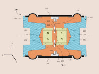
In the present invention under review, Thigpen addresses the high-frequency limitation of his original device. The improved system includes stiff vanes that are rigidly attached to a hub with an additional torsional actuator (element 66 in Figure 2) provided in each vane. The torsional actuator can vary the pitch of the outer portion of each vane significantly more than the root portion. The outer portion travels through a greater arc length per revolution of the transducer than the root portion, therefore the angular deflection is provided where the swept area and velocity is greatest. This increases the transducer’s output, including higher frequencies that would have been attenuated in the earlier system.
In addition, since only a portion of the vane is being twisted, inertial effects are minimized, which enables the restoring force, due to vane stiffness, to more rapidly restore the untwisted state and the blade becomes easier to pitch at frequencies near the torsional natural (resonant) frequency. This results in higher input frequencies being reproduced by the transducer without losing significant amplitude. Combining the new torsional actuator structure with new advanced, high stiffness materials, such as carbon fiber, the new improved system is said to be able to substantially advance the high frequency capability to frequencies between 200Hz and 2kHz.
Thigpen has been working on this type of device for more than a decade and has advanced what was already a very difficult engineering achievement, to a more sophisticated structure that apparently raises the general performance and high frequency limits beyond what was thought possible with this architecture.
There are still a number of fussy elements to this type of system, including what type of back chamber volume is required to achieve the low frequency potential. Many are mounted in floors or walls depending on back rooms, basements and attics to provide very large back wave volumes similar to large woofer, infinite baffle systems mounted in floors or ceilings.
Earlier work in the late 1980s at Solution Matrix, Inc. (SMI), using Piezo film on the blades to change pitch at the audio rate, we were able to achieve output at a much higher rate of change as compared to the dynamic voice coil driver approach, albeit with somewhat less pitch displacement. Hybrid devices may be of value using piezo film on the fan blades for higher frequencies and dynamic voice coil drive to rotate the blades at lower frequencies.
Ultimately, Bruce Thigpen realized an impressive achievement with his original system and now the improved versions, all of which develop low-frequency output that creates a listening experience that is quite remarkable compared to most conventional subwoofer approaches. Well done. VC
This article was originally published in Voice Coil, July 2017.