Loudspeaker for Eliminating a Frequency Response Dip
Patent Number: US9113244B2
Inventor: William Decanio (Castaic, CA)
Assignee: Harman International Industries, Inc. (Stamford, CT)
Filed: May 10, 2013
US Classes: 381/386
Published/Granted: November 13, 2014
Number of Claims: 20
Number of Drawings: 10
Abstract from Patent
In at least one embodiment, a speaker system is provided. The speaker system includes a speaker enclosure having a front end, a rear end, and a first transducer. The front end is arranged to face a listening area. The rear end is arranged for being mounted to a mounting surface. The first transducer is positioned within the speaker enclosure for facing into the mounting surface such that the first loudspeaker transmits acoustic energy from the rear end towards the mounting surface to prevent a frequency response dip with the transmitted acoustic energy.
Independent Claims
1. A speaker system comprising: a speaker enclosure including: a front end for facing a listening area; a rear end for being mounted to a mounting surface; and a first transducer positioned within the speaker enclosure for facing into the mounting surface such that the first transducer transmits acoustic energy from the rear end towards the mounting surface to prevent a frequency response dip with the transmitted acoustic energy.
13. A speaker system comprising: a speaker enclosure including: a front end for facing a listening area; a rear end for being mounted to a mounting surface; and a first transducer positioned within the speaker enclosure for directly facing into the mounting surface such that the first transducer transmits acoustic energy from the rear end directly into the mounting surface to prevent a frequency response dip with the transmitted acoustic energy.
20. A speaker system comprising: a speaker enclosure including: a front end for facing a listening area; a rear end for being mounted to a mounting surface; and a transducer positioned within the speaker enclosure for directly transmitting acoustic energy from the rear end into the mounting surface to prevent a frequency response dip with the transmitted acoustic energy.
Reviewer Comments
In 1970, Roy Allison and Robert Berkovitz, while employed at Acoustic Research, delivered an Audio Engineering Society (AES) paper, “The Sound Field in Home Listening Rooms.” The paper was based on research measuring two different models of Acoustic Research loudspeakers (AR-4x and AR-3a), from five different angles, in eight different listening rooms, at 22 different listening positions. The average spectral balance of the 22 listening positions were generally smooth, or had smooth deviations, except for an unexpected, v-shaped notch consistently appearing near 200 Hz.
After departing from Acoustic Research, Allison pursued further research into the specific cause of, and possible solutions to, this observed aberration. In parallel with his own research, Allison looked for historical literature on the subject and found that the issue had already been well characterized starting more than a decade earlier in three papers published in the Journal of Acoustical Society of America (JASA). The papers, written by Richard V. Waterhouse, were titled “Interference Patterns in Reverberant Sound Fields” (1955), “Output of a Sound Source in a Reverberation Chamber and other Reflecting Environments” (1958), and “Interference Patterns in Reverberant Sound Fields II” (1965).
[As an aside, it is interesting that to get a head start regarding acoustical issues, usually one merely has to dig into a stack of historical JASA papers. Surprisingly often, they explore subjects that appear exotic (and go unnoticed) at the time, only to have the significance “discovered” by the audio industry more than a decade later. In addition to the Waterhouse / Allison case mentioned earlier, I selected two random examples (out of many) to illustrate my point. P. J. Westerfelt characterized Parametric Loudspeakers in the JASA in 1963, more than a decade before Panasonic started development of them in 1979. A. L. Van Buren, et al. wrote JASA papers on Constant Beamwidth Transducers (CBTs) starting in 1978 more than a decade before Don Keele’s presentation of CBT arrays at the 109th Audio Engineering Society (AES) Convention in September 2000.]
In his 1974 AES paper, “The Influence of Room Boundaries on Loudspeaker Power Output,” Allison delivered the results of his research findings and solutions relative to the near boundary interaction issue wherein he suggested that for the frequency of a transducer spaced 1/4-wavelength from a single boundary, a round-trip transit path to the wall and back to mix with the direct sound is 1/2-wavelength and therefore is out of phase with the direct sound, causing a cancellation dip in the amplitude response corresponding to the dip observed in his original 22 listening position study.
Significant to the patent application under review, Allison’s first solution to the single-boundary problem is shown in a figure on page three of his paper, which is to turn the loudspeaker around and have the low-frequency transducer face the boundary with a spacing of about 2" from the wall. With this positioning of placing the transducer such that is so intimate with the wall that the direct and reflected sound are very close to zero phase differential. Therefore, the cancellation dip is substantially eliminated.
Unfortunately, this arrangement causes the transducer diaphragm and the boundary surface to form a conical horn flare in the space between, causing a peak (also shown in Allison’s paper) that is much greater in amplitude than the dip that is removed. All this leads up to the current patent application under review.

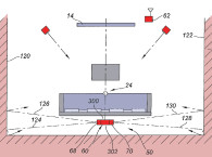
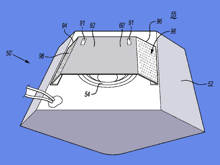
Figure 1 (which is also designated as Figure 1 in Allison’s paper) illustrates a standard prior art boundary coupled loudspeaker configuration with the direct and reflected paths to the listening position and the associated difference in path lengths, which will cause what is often called the “Allison-dip.”
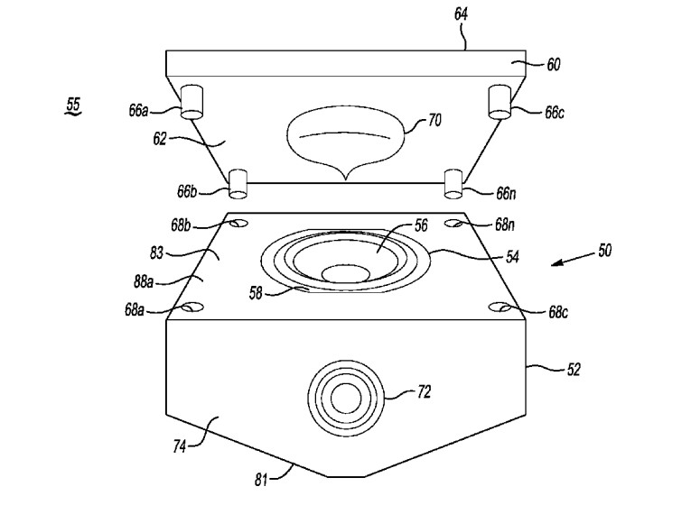
Figure 2 (which is known as Figure 3 in Allison’s paper) shows the disclosed inventive solution of orienting the low-frequency transducer (covering the low frequencies to at least lower midrange range frequencies of the loudspeaker system) to face the front wall (or ceiling) boundary at a preferred spacing of between 0.5” to 1.5”, with additional upper range drivers mounted on the enclosure’s surface facing away from the boundary.
As in the first solution example in the Allison paper, this approach minimizes or eliminates the dip that is normally located in the 200-to-600-Hz range. But also, as in the first Allison solution example, the application discloses the peaking artifact of an approximately 12-dB peak at 800 Hz.
To address this secondary effect, some embodiments of the inventive concept include a filter for minimizing or eliminating the frequency peak caused by the cavity loading between the low frequency transducer and the boundary surface.
From at least the 1960s, it has been fairly common to use slot loading of a woofer system to be boundary coupled to a mounting surface, which was most often the floor, front wall, or corner. These systems almost always had a frequency response that was characterized by amplitude peaking in the lower midrange. These systems required either low-pass filters of adequate slope or a low-pass filter combined with a narrowband notch filter centered on the frequency of peaking.
Because of the prior art solution disclosed and characterized in the Allison paper, and the commonality of prior art slot-loaded, boundary-coupled woofer systems, with associated filters to eliminate associated cavity-based peaking, this concept’s novelty must be questioned, relative to patentability. One of the more subtle design issues with this type of single-boundary coupling is that if one tightly couples the low-frequency transducer to one boundary (within a couple inches or less), then in many cases, it can have even more severe response ripple from the next closest boundaries, such that some floor-loaded woofer systems can result in a significant dip in the frequency response from the 1/2-wave differential interference reflection from a ceiling or front wall surface.
If one closely couples the woofer transducer to at least two boundaries (e.g., a floor and a front wall) the most susceptible remaining sidewall and/or ceiling boundary reflection can cause an even more severe dip in the response. One of the advantages of keeping the low-frequency transducer from being too tightly coupled to any of the boundaries, is that one can distribute the distances to each of the boundaries so that they are not equal in length, and do not have lengths that are exact multiples of each other. By doing so, you create a diversified summation of direct sound and reflected sound distances as they arrive at the listener, with a resultant amplitude response that is substantially ripple-free up through the lower midrange.
That said, the proposed concept can be a very effective approach to optimizing a loudspeaker enclosure for smooth response with a boundary-coupled placement (particularly if the system is also placed purposefully relative to the remaining nearby boundaries). Additionally, the configuration can have other positive attributes, including increasing low-frequency efficiency and output by capitalizing on +3 of boundary gain at frequencies for which the coupled boundary is less than 1/10 of a wavelength from the low-frequency transducer. VC
This article was originally published in Voice Coil, January 2015.