All-pass filters are perhaps one of the most overlooked and misunderstood tools for the general audio practitioner. Much has been written about their use to yield more linear phase response through the majority of a loudspeaker’s passband. They can also be used to optimize the directivity and magnitude response of a loudspeaker system. Perhaps we should first look at just exactly what an all-pass filter is.

Background
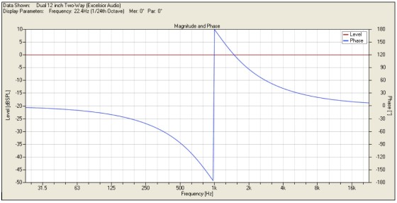
You are familiar (or at least should be) with low-pass and high-pass filters. As their names imply, they pass one part of the audio spectrum while attenuating the others. They are the basis for loudspeaker crossovers. As with any analog filter, there is phase shift associated with the change in output magnitude of these filters. Examples of these are shown in Fig. 1 as fourth-order Linkwitz-Riley filters.
There are, of course, other ways to construct all-pass filters. They can be defined mathematically, just as low-pass and high-pass filters can be. They can be of different orders (i.e., 1st, 2nd, 3rd, and so on) and have specific alignments (Butterworth, Bessel, Linkwitz-Riley, and more). These alignments are not defined by the shape of the magnitude response at the corner frequency of the all-pass—as you typically think of low-pass and high-pass filters—but by the shape of their phase response at the corner frequency.
Low-pass and high-pass filter alignments can also be defined this way.
One difference about all-pass filters is that for each order there is 180° of total phase shift. Low-pass and high-pass filters have only 90° of total phase shift for each order. The importance of this distinction will become clear later.
two way loudspeaker system.
Loudspeaker Responses
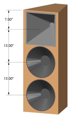
Now that you have a basic understanding of an all-pass filter, let’s put one to good use. Suppose that you have a two-way loudspeaker system composed of a high-frequency horn and dual 12″ woofers as illustrated in Fig. 3. The horn is located at the top of the baffle. One woofer is directly below the horn. The second woofer is directly below the first. This is a fairly typical configuration.
To keep things simple, I will model these components as point sources. This will make it easier to see anomalies in the directivity response of the system when the individual sources are combined. The horizontal symmetry of my example loudspeaker assures me that nothing spectacular will occur in the horizontal plane. Having the sound sources displaced vertically will yield some interesting behavior.
Because all of the good stuff will happen in the vertical plane, I will be looking primarily at vertical directivity maps and a few polar plots. The nice thing about a directivity map is that it allows you to look at the relative level of different radiation angles at all frequencies at the same time, whereas polar plots allow you to see the relative level of different radiation angles at only a single frequency. Ideally you should see the same level at all frequencies and at all angles because you are using point sources (which have no inherent directivity).
This will not be the case due to the vertically spaced sources. Incidentally, all of the modeling was performed by, and most of the graphs generated with, the new SpeakerLab/GLL software from AFMG (www.afmg.eu). It allows for some very nice investigation and optimization work to be carried out and displayed.
Linkwitz-Riley crossover.
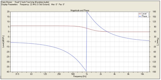
I have ideal textbook sources, so I will use fourth-order Linkwitz-Riley low-pass and high-pass filters with a corner frequency of 1kHz for the crossover. The on-axis summation of the sources in the far field with these filters is shown in Fig. 4. This is exactly what you would expect.
The low-frequency level is +6dB compared to the high frequency with a smooth transition in the crossover region. This level change is because of the two woofers compared to the one horn (the point sources you are using each have identical output). You also notice 360° total phase shift due to the fourth-order filters. You get 90° of phase shift for each filter order.

Looking at the off-axis response shown in Fig. 5, you see that things are not quite as well behaved. There is considerable cancellation off-axis from 500Hz up through the crossover region. The directivity map has frequency plotted on one axis and the vertical radiation angle on the other axis. The output level is shown both as color variation and as elevation above the frequency-radiation angle plane.
All of the off-axis response data is normalized to the on-axis response. A slice through this surface at a given frequency will yield the polar response at that frequency. Similarly, a slice through any radiation angle will yield the frequency response at that angle relative to the on-axis response.
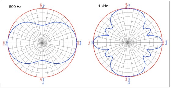
For reference, polar plots at 500Hz and 1kHz are shown in Fig. 6. Notice the deep nulls at +90° and –90° (straight up and down) in the 500Hz polar and the same depressions in the directivity map (-20dB green region). Also, at 1kHz the level drops quickly at off-axis angles, increases a bit, drops again, and then increases back to full level. You can see this in the rippling of the directivity map. Compare this to the 1kHz polar plot.
The cause of this destructive (cancellation) and constructive (addition) interference is that multiple sources in different locations are radiating in the same frequency region. At crossover (1kHz) all three devices are active. The largest separation of sources is between the horn and the bottom woofer. This distance is 26″, which is almost exactly two wavelengths at 1kHz.
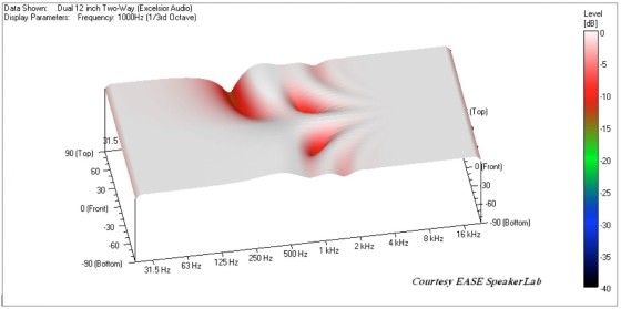
and 2nd-order 300Hz LP filter on the bottom woofer.
The distance between the horn and the top woofer is 13″, as is the distance between the two woofers. This is almost exactly one wavelength at 1kHz. This is why there is such good summation above and below (+90° and –90°) the loudspeaker. The woofer spacing is the cause of the decrease in output above and below the loudspeaker at 500Hz. This distance is almost exactly one-half wavelength at this frequency.
To minimize these directivity problems, you need to minimize the interference by attenuating a source so that only one is active within a given frequency region. You can do this with the woofers by placing another low-pass filter on the bottom woofer (in addition to the existing 1kHz low-pass filter used for the crossover—this is commonly known as a 2.5-way design). I’ll use a second-order Butterworth low-pass filter at 300Hz to roll off the higher frequency output of the bottom woofer. The effect of this on the vertical directivity is shown in Fig. 7.
The two off-axis cancellations (depressions) around 1kHz are due to the crossover in this region between the top woofer and horn. The only way to eliminate these cancellations is to eliminate the spacing between the top woofer and horn. That is, they would need to occupy the same point in space, which is clearly impossible.
Arranging them coaxially would not eliminate the cancellations, but it would change the angles at which they occur.
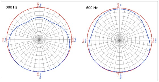
and 2nd-order 300Hz LP filter on the bottom woofer.
You also see something very peculiar. In the 250–500Hz region the directivity map is not symmetrical. There is a large region of cancellation above the loudspeaker. This is also shown in the polar plots of Fig. 8. Notice the output is greater below the loudspeaker than it is on-axis.
Some practitioners may be thinking, “No big deal, I want more output directed down toward the audience from flown loudspeakers anyway.” This is true, which is why flown or elevated loudspeakers are usually tilted downward and aimed at the audience. This “downward lobe” remains pointing along the vertical axis of the enclosure. When tilted down, this axis is usually pointing toward the stage area. Starting to see the problem?
How many line array cabinets on the market have dual woofers or midrange drivers placed on opposite sides of the enclosure? These same directivity problems will also plague these line array cabinets, but because the drivers are offset horizontally they will occur in the horizontal plane, not the vertical. I certainly don’t want to try to cover an audience area with a loudspeaker system that suffers from horizontal asymmetry over only a portion of its passband. This asymmetry of the directivity response is not caused by one of the woofers having more output than the other. The bottom woofer is the one that has been attenuated and the main lobe is pointed down, not up.
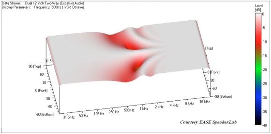
2nd-order 300Hz LP filter on the bottom woofer, and 1st-order 300Hz AP filters
on the top woofer and horn.
This lobe and its asymmetry are caused by the phase shift introduced by the additional low-pass filter on the bottom woofer. The bottom woofer now has a different, and non-complementary, phase response compared to the top woofer and the horn. To correct this all three components need to have complementary phase response.
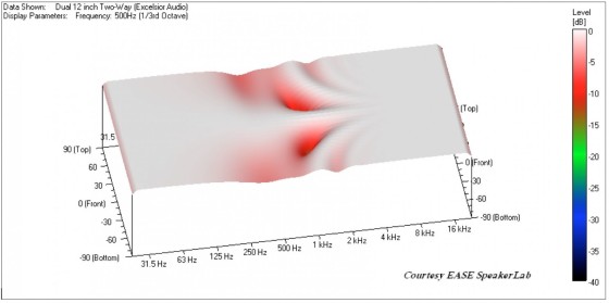
woofer and horn.
Application
You need to add phase shift to the top woofer and horn without altering their magnitude response. This is when you grab an all-pass filter. The 300Hz low-pass filter is second-order, yielding 180° of additional phase shift. To match this you need a first-order all-pass filter for the top woofer and the horn. When you apply these filters, you get the results shown in Fig. 9. The vertical directivity is once again symmetrical. The off-axis cancellations have been greatly improved when compared to Fig. 5 and Fig. 7.
You can further improve this by using a higher order low-pass filter on the bottom woofer to more rapidly attenuate its higher frequency output. I will change from the second-order Butterworth to a fourth-order Butterworth filter. You must also change the all-pass filters on the top woofer and horn from first-order to second-order Butterworth. Once you use an all-pass filter greater than first-order, you must be sure to match its alignment, or Q, to that of the low-pass filter so the phase response of the low-pass and all-pass filters is identical. These changes give the results in Fig. 10.
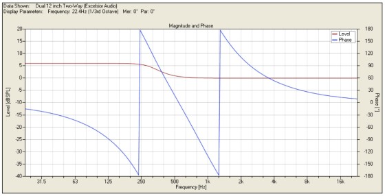
The on-axis magnitude response for these final filter parameters is shown in Fig. 11. Compared to Fig. 4 there are only two differences. The transition from +6 to 0dB output occurs in the 250–630Hz region instead of the 630Hz–2kHz region. The other is that there is one additional phase rotation in the transfer function of the loudspeaker system. While this latter difference is not ideal, it is certainly a small price to pay for the improvement in directivity response from that of Fig. 5 to Fig. 10. I hope this has helped to illustrate one application of all-pass filters being used effectively to improve the directivity response of multi-driver loudspeaker systems.
Originally published by Voice Coil, February 2010
Author: Charlie Hughes, Excelsior Audio Design & Services, LLC


