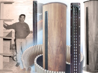
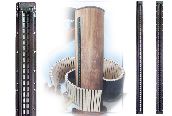
In January and February 2001, audioXPress included this remarkable project from Thomas Perazella. Published in two parts, the articles described in detail the design and construction of a speaker using the Bohlender Graebener RD-75 planar magnetic driver, including references to previous experiments with dipole baffles. You can read the first part here.
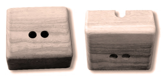
Construction of the box was very simple. I cut four pieces of walnut for the sides, and one piece for the top. I glued and clamped the four side pieces and the top. After the top dried, I rounded the edges of the box with a disc sander and drilled mounting holes. I routed the back sides of the holes to allow attachment of the nuts. Looking back, I should have gotten the longer versions of the binding posts, BP1.5, which would have eliminated the routing.
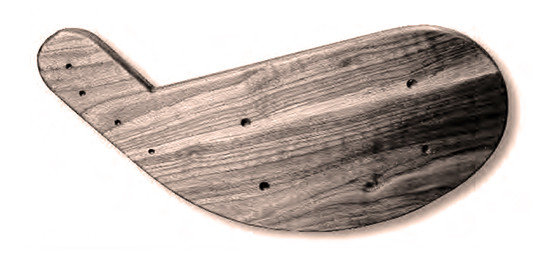
Photo 20 is a top view of the box. To provide an exit path for the wire, I cut a slot in the back side of the box, which is the side that would face the driver. Using a slot eliminated threading wires through holes. I also drilled pilot holes for mounting in the bottom edges of the box using the base template. Photo 21 shows the wire slot.
Final Prep
Veneering the baffle was the next step. The walnut veneer I chose was quite a bit heavier than the paper-based types used in some applications. The greater thickness provided a smooth, ripple free surface when used over the Kerfkore.
However, it was still sufficiently flexibile to wrap around the half-round on one side of the mounting plate. At this point, I got cold feet; the thought of working with large, expensive sheets of veneer on top of two large, expensive sheets of Kerfkore — into which many hours of work had gone — led me to look in Dave’s direction with worried, pleading eyes. Dave came to the rescue. He not only applied the veneer, but also routed it to match the driver opening in the mounting plate. Thank you very, very much Dave!
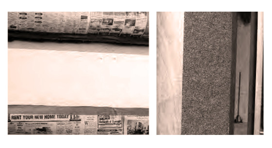
The last stages of the assembly before finishing were to paint the unveneered, non-hardwood pieces with flat black paint, add foam to the interior cavities of the baffle, and mount carpet to the back plate. Photo 22 shows the baffle masked before painting. In order to prevent internal resonances in the cavities formed by the ribs and outer covering, Rudi suggested filling them with insulating foam. I decided to use the canned version available at the local hardware store (used to seal around window frames and electrical outlet boxes). This material is easy to use and readily available.
To apply the foam, I inserted the tubing supplied into holes previously drilled into the bottom corner of each cavity. I then released the foam into the cavities. After using more than two cases of the foam, I realized that, were I to do this again, I would use an alternative approach. The first would be to find someone who had an “Insta-Pak” machine, used by professional packers and is essentially a high-volume version of the home spray cans. They are refillable, and foaming this way is much faster and more economical. Another approach would be to buy blocks of foam and insert them into the cavities before applying the Kerfkore.
Before applying the carpet, I first cut it to size and then test-fitted it on the baffle. I purchased the carpet from Parts Express; it has a latex backing, making application easier. After I completed the sizing, I sprayed the back plate and carpet backing with 3M #77 adhesive. Once the adhesive was tacky, I applied the carpet and allowed it to dry. Photo 23 shows the carpet in position.
The Finish
The last operation before final assembly was the finishing of the veneered surfaces and the top and bottom plates. Regardless of the finish applied, the most important step in any finishing operation is to properly prepare the wood. Translated, that means to sand, sand, and sand again with progressively finer grits of sandpaper. I did the preliminary sanding on the solid pieces with a belt sander. Following that I used an inline sander, and finally, hand sanding. For the veneer, I eliminated the belt sanding.
Picking a finish is a matter of personal choice. When using high-quality hardwoods, I’ve always preferred a straight oil finish. Good hardwood has natural colors and shadings that can often stand on their own without help from a stain. Using a stain, may, in some cases, hide the natural beauty of the wood. In addition, oil provides a low gloss shine with a deep luster that says “real wood”; plastic need not apply here.
For this project, I decided to use one of my old favorites, Watco Danish Oil. Before proceeding, I took scraps of the veneer and solids, sanded them, and then applied the oil. It never ceases to amaze me how wood transforms as you apply the first coat of oil. The grain and natural color of the wood seem to leap out at you. Properly finished real wood is, as Martha would say, “a good thing.”
After several sandings and coatings of oil on the sample pieces, I decided the tone I preferred could be obtained with the oil alone. For the solids, three coats were necessary. The veneer required four coats to achieve the same effect. For some reason, the veneer seemed to absorb more oil than the solids. If you have never done an oiled finish, it is actually uncomplicated, but rather labor intensive. After you properly sand the surfaces, vacuum them and finish by wiping with a tack cloth. Next, liberally apply the oil to the wood using a clean rag, and wait around 30 minutes for the oil to soak in. Do not be stingy with the oil, since the wood will absorb quite a bit.
If you do not, spontaneous combustion is a very real possibility. It would be a shame to burn down your house with your newly built speakers inside.
Final Assembly
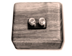
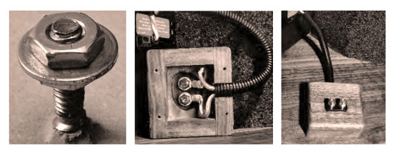
I began the final assembly by mounting the Vampire binding posts in the terminal blocks. I inserted the blocks into the mounting bases and then through the holes in the blocks. I then fastened them, using the nuts supplied. Photo 25 shows the posts mounted on a block. Before attaching the top and bottom plates and the drivers, I moved the baffles to my listening area in the loft where I planned to use them. This reduced the weight and bulk of the baffles and made it a two-person job. The drivers would have added another 35 pounds to the baffle, making the job quite a bit harder.
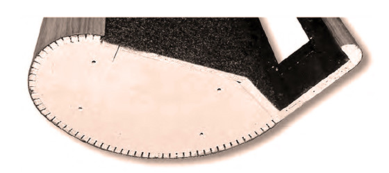
Once in the loft, I added the tops. Photo 26 shows the finished baffle on the floor of the loft in preparation for the addition of the top. Note the four holes for the 1/4” × 20 T-nuts. The pilot holes for the wood screws are not as visible. For the tops, I used four 1/4” × 20 flat head Philips machine screws to mate the Tnuts, and I used four #8 flat head Philips particleboard screws to mate with the driver mount and half round.
I began the fastening by aligning the holes in the top with the pilot holes, and inserting the four 1/4” × 20 screws loosely into the T-nuts. Next, I inserted the four #8 screws through the top into the pilot holes and tightened them. Finally, I tightened the machine screws. Photo 27 shows a top being installed.
I used four 1/4” × 20 furniture bolts and four #8 flat-head Phillips particleboard screws to fasten the bottoms to the baffles. Furniture bolts are different from ordinary bolts in that they have wide, relatively thin heads. This allows the clamping force to be spread over a relatively large area, while maintaining a low profile. The heads are also round so that they won’t snag carpeting if you slide the bases around for positioning.
To tighten them, a recessed hex opening is provided in the center. Photo 28 shows a bottom being fastened to a baffle. Also visible in the photo are the furniture glides I installed around the perimeter of the base. The assembly sequence is the same as for the top, except for the substitution of the furniture bolts for the machine screws.
Connections
The lead wires of the RD75s were a little too short to reach the terminal blocks once I mounted the blocks on the base. I made extensions using #12 speaker wire and added them to the speaker leads. To enhance the appearance of the cables, I purchased a length of the split black corrugated plastic sheathing used to route wires underneath a car hood from my local auto parts store. Since it is split its entire length, it is an easy task to slip over existing wires and provides a much more professional look. I added ring lugs to the leads for later attachment to the binding posts.
A word about crimping is in order. I’ve heard others mention that they solder their connections instead of crimping them, since that results in a better connection. Wrong! To see really good connections, look to the power distribution business, which must handle currents in the range of thousands of amps.
At a company where I once worked, we used 500 MCM wire (that’s big) to distribute power in TV studio applications. These connections required such low resistance that the main distribution bus bars were silver-plated at the points where the connectors were bolted to them. All connectors were crimped to these wires using a hydraulic crimper.
One day, just for grins, I decided to cut apart one of the crimped connectors to see whether I could find any voids. Not only were there no voids, but the joint looked like one solid piece of copper. A good crimp actually causes the connector and wire to flow together, resulting in much lower resistance than a solder joint. You are more likely to wind up with a cold solder joint than a bad crimp if you use a good crimper.
My advice is to spend money on a good compound action, ratcheted crimper and a few sets of the proper dies and crimp your connections. You’ll probably spend around $100 and have a lifetime of good connections with no melted insulation.

Driver mounting
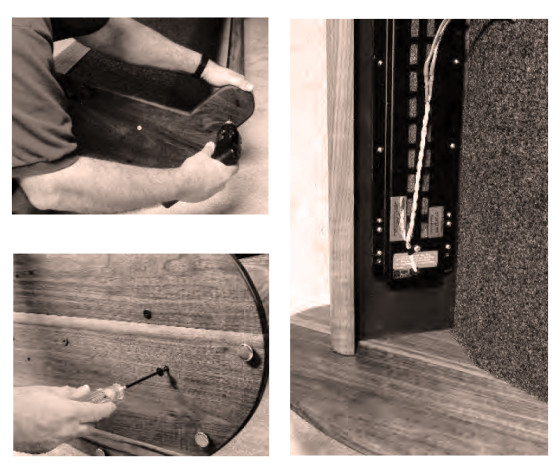
Next, I mounted the RD75s to the baffle. I positioned the drivers on the rear of the mounting plates and made marks through the mounting holes for drilling pilot holes. I removed the drivers and made pilot holes using a drill stop. Failure to use a drill stop could result in ugly holes through the veneer if you drill too deeply. Photo 29 shows a driver in position for marking.
The driver mounting hardware I chose included 10 × 24 hanger bolts, #10 flat washers, #10 lock washers, and 10 × 24 nuts. Hanger bolts have a wood screw thread on one end and a machine screw thread on the other (Photo 30). The advantage of a hanger bolt is that you can insert a machine screw stud into a blind hole in a wood substrate. There is no need to drill a through hole as you would with a screw or bolt. Once the hanger bolt is in place, you have the advantage of a machine screw in a wooden piece; that is, you can fasten or unfasten the device without damaging the wood.
To insert the hanger bolts into the mounting plate on the machine screw end, apply a nut, flat washer, and then another nut. Tighten the nuts. Then you can insert the wood screw end of the bolt assembly into the pilot hole and tighten with a wrench. Photo 31 shows a hanger bolt in the process of insertion.
Do not drive the bolt too far into the wood or you will have a dimple in the veneer on the other side of the hole. Once the bolt is seated, you can remove the nuts and washer by placing a wrench on the lower nut and then loosening the upper nut with another wrench. Remove the two nuts and washer. Repeat the procedure for all the bolts. After all the bolts were in place, I carefully positioned the mounting holes in the drivers over the hanger bolts and lowered the drivers into place. The drivers are heavy. If you do this, be careful not to drop the driver on a hanger bolt. Then fasten the drivers in place.
Once I secured the drivers to the mounting plates, I fastened the driver leads to the binding posts in the terminal blocks. Photo 32 shows the bottom of a terminal block with the wires attached. The pilot holes for mounting the block, as well as the black corrugated cable sheathing, are also visible. The last assembly step was to fasten the mounting blocks to the base plates. For this, I used #6 flat-head Philips wood screws. Photo 33 shows a terminal block mounted to a base. The only thing left to do was to raise the baffles into an upright position and slide them into place.
Power-up
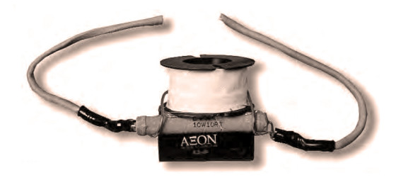
The RD75s are supplied with passive filters (Photo 34), consisting of an air-core choke, a film capacitor, and a resistor, that introduce a notch in the response where the drivers exhibit a cavity resonance. Since I was using active equalization and a separate amplifier to directly drive the RD75s, I did not wish to introduce any unnecessary impedance in the circuit and decided not to use the passive notch filter. Instead, I used a pair of Orban parametric equalizers to precisely correct the cavity resonance.
To do that, I used an ACO Pacific 7012 mike feeding LAUD measurement software, with LAUD used in the repeated or cycling FFT measuring mode. The center frequency, Q, and level parameters of the Orbans were adjusted until LAUD produced a flat frequency plot. Parametric equalizers and computer measuring systems can really make life easy.
BG claims a response down to 150 Hz for the RD75. To ensure high power handling (without overload due to displacement limitations), I decided to set the crossover for the RD75s at 250Hz using a 12dB/octave slope. I was already using a custom four-way electronic crossover for my then-current system, which used 7″ Eton midranges and Heil AMT tweeters to cover the range from 400Hz up. I modified the high-pass section to provide the 250Hz point for the RD 75s and dropped the high end of the bass bandpass section from 400Hz to 250Hz.
The old midrange bandpass section was not used, effectively making it a three-way crossover. This also freed the tweeter amplifier. The RD75s are driven by a modified Hafler DH500, formerly used for the Etons.
The moment we all wait for had arrived. I was ready to listen. For the first selection, I used a CD that I knew would test the BGs, “Steppin’ Out” with Tony Bennett. Ralph Sharon plays some great piano sections on a Bosendorfer. The intro to the second track, “Who Cares?” is especially good.
From the first note, I knew that I was in for something special. The sound of the piano was warm, dynamic, and detailed. I had never heard anything as good, short of live sound. I was in heaven. A few minutes into the cut, however, I heard something rough on a few of the louder passages. It must have been my imagination; the rest of the piece was just great.
The next piece was Pink Floyd, “The Wall.” This is a very complex album, and the BGs revealed detail I had never heard before. The sense of room space in the intro of the cut “One of My Turns” was the most realistic I had ever heard. While listening through the various cuts, however, I thought I heard
occasional harsh spots. I kept thinking to myself that it could not be. I spent all this time, money, and sweat to produce these masterpieces; there couldn’t be a problem. Not being one to stick my head in the sand for extended lengths of time, I decided to do some quick tests. I ran some separate sine-wave sweeps on each driver.
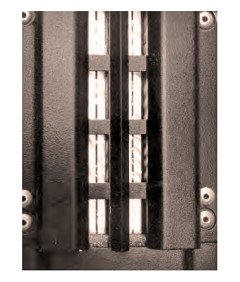
This can be a very revealing test, and reveal it did; both drivers had rather strong resonances at multiple frequencies starting at 110Hz in one sample and 470Hz in the other. I noticed that both drivers had what appeared to be ripples in the diaphragms (Photo 35). I wasn’t sure whether these ripples were the problem, but it was time to call Rudi. He was surprised as he had never encountered this problem before, but immediately agreed to replace them.
BG sent out replacements, and I packed up the originals in the same carton and returned them. The new drivers showed no traces of the ripples that were in the first samples. I ran sweeps again and noticed no resonances (other than the expected cavity resonance characteristic of the driver). After mounting the drivers in the baffles and putting them back in position, I put the Tony Bennett CD back in, sat down, steadied my shaking hands enough to hit the play button and waited the hours (read two seconds) for the piece to begin playing.
Getting through each note was agony. Everything seemed like a slow-motion nightmare as I waited for the bad sounds that I had heard before to re-appear. There was nothing except glorious sound! The occasional bad sounds I heard before were gone. What was left was the most detailed, dynamic sound that I had ever heard, at whatever level I tried. The sound stayed clean up to the point that the custom speaker protection network that I use disconnected the drivers, and that was in excess of 110dB.
Critique
Normally, at this point I would describe the characteristics of the sound that I heard with various types of music. However, thinking about it, that doesn’t make sense in this case. Regardless of the music I listened to — be it rock, classical, folk, blues, jazz, new wave, or whatever—a common set of characteristics came through.
First, there was a sense that you were in the presence of the performers. Subtle details that were masked by my (very good) previous system were now present. The effect was quite different than the sense of forwardness you get when the frequency balance is skewed toward the highs. Rather than parts of the sound hitting you in the face, there was a sense of texture coupled with smoothness that presented a more complex, yet more understandable, rendition of the performance. Whether it was a flute, trumpet, harp, violin, piano, voice, synthesizer, or effects recording, the effect was the same—greater realization of the subtleties of the acoustic output being produced by the source.
Second, that transparency was available at all levels, not just at middle levels, as often happens with some drivers. Whether listening at whisper levels or full rock blast, the sound never became congested. The ability to have this kind of dynamic range does wonders for establishing a lifelike listening experience. Mini monitors need not apply in this category. This has to do with the volume displacement issues that we often think of when trying to get good bass. However, volume displacement is an issue at any frequency.
The volume displacements required for a given SPL decrease with increasing frequency, but as the SPL requirements increase, so do the volume displacement requirements at all frequencies. Small area mid- and high-frequency drivers need more displacement to meet the demands of high SPLs. This can place them out of their linear operating range. The large surface area of the RD75s means less displacement for a given SPL, or conversely, the capability to reproduce higher SPLs before reaching a nonlinear operating range.
Third, the sense of space and placement was exceptional. I’ve often heard that dipoles can’t image. Hogwash! Place a dipole close to a rear wall where the back wave output is perceived as early reflections and you’ll have problems. However, placing any speaker near a wall, or for that matter near the ceiling or floor, is looking for trouble. Dipoles have an advantage — there are nulls to the sides, reducing problem reflections from walls.
The RD75 also behaves as a line array because it is so long with respect to the wavelengths being reproduced. This results in a cylindrical wave launch instead of the spherical wave launch that you get from a small dynamic driver. The severe cutoff of output above and below the long axis of the RD75 very effectively reduces floor and ceiling interactions.
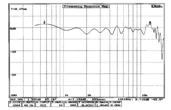
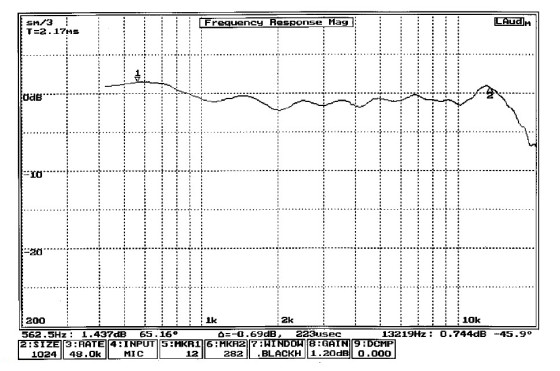
I took measurements of the finished RD75/baffle combination with LAUD. The un-smoothed 1m frequency response curve is shown in Fig. 1. The response is very smooth up to 13kHz, but beyond that, there are some ripples with a decrease in response beyond 16kHz. The commonly reported 1/3 octave smoothed response is shown in Fig. 2. Except for the 13kHz bump, the response is generally within ±1.5dB out to about 15kHz.
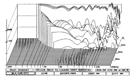
My guess is that the controlled directivity caused by the large size, and often dipole configuration, result in fewer early reflections from nearby surfaces and this is interpreted as greater detail. Certainly, I have had other conventional drivers that had spectral decay plots that have looked as good as the RD75s, but did not have the apparent detail.
Cost
What was the final cost of these speakers, excluding my labor?Just over $1700. That may seem like a lot, but considering the RD75 forms the basis for speakers in the $15,000 to $125,000 range, I consider it a bargain. The costs break down as follows:
1. Two RD75 drivers including shipping $895.00
2. One 4 × 8′ sheet of 3/4" MDF $30.00
3. Two 4 × 8′ sheets of Kerfkore $257.08
4. Two 4 × 8′ sheets of walnut veneer $210.30
5. Solid 1″ walnut planks $131.16
6. Latex-backed carpet $21.05
7. Miscellaneous glue, hardware, tape, oil, foam, etc, $95.00
8. Two pairs of Vampire BPHEX binding posts 63.00
Total $1,702.59
Having lived with the RD75s for quite some time now, I can honestly say that they have come closer to my idea of a “perfect” speaker than anything else I’ve ever had. So where did the title of this article come from? If you heard them you would think that the music was so true and pure that it came directly from heaven on angels’ wings. In this case, the wings are man-made, but the results are the same.


