Cadillac did not invent the very first automobile but reinvented it into their concept of what a car should be. Likewise, I did not invent the first vacuum tube mu-mode (constant current) voltage gain stage; but rather I re-invented the mu-mode gain stage into my specific types, collectively called Mu Stages. It began with testing the so-called shunt regulated push-pull (SRPP) gain stage, and the process of how the mu stage evolved from that is described in my first Mu Stage article. Altogether now there are at least three generations or categories of the Mu Stage. The vast majority of those who heard a mu stage heard only the Type 1 (aka Mu1) and raved about its sound quality. I estimate that the latest generation Type 3 (Mu3), as presented in this article, to be the best and most unique Mu Stage to date.
A Breakthrough
When you hear live music, even if you are blindfolded you would know it is live music because your ear does not lie. Hindering the realistic reproduction of live music are conventional “textbook” audio gain stages, which dominate not only electronics in general, but so much of audio as well. Conventional audio circuitry tends to produce conventional sound quality, resulting in the universally well-known listener fatigue. The Mu Stage was developed primarily to prevent listener fatigue by peeling away as many veils as possible, bringing the music closer to the listener.
A Mu Stage is an innovative vacuum tube or hybrid audio gain block that can serve as the basis of exemplary amplifiers, preamplifiers, studio microphone preamps, line stages, anywhere an audio gain block is needed. This article introduces the Mu3 stage or third-generation mu stage, which retains the advantages of previous mu stages including low distortion, wide bandwidth, low output impedance, large voltage swing capability, but most importantly realistic sound reproduction. The Mu3 stage is a very versatile high-fidelity audio gain block.
This stage is called a Mu Stage because the triode voltage amplifier tube V1 operates at constant current, which increases the stage gain to the tube’s published amplification factor mu (Greek letter μ). However, two much more important things happen when V1 operates at constant current: V1 yields the greatest possible audio fidelity of which it is capable. Also, the tube’s inherent distortion is minimized. When all this happens, I like to say V1 is “muing” (a new word).
A Mu Stage can take many forms, but they all work essentially this way: A vacuum tube triode voltage amplifier V1 is provided a constant plate current, as well as output buffering, by supporting pentode cathode follower V2 (or solid-state unity gain follower). The more constant the current V1 is provided, the more revealing and truthful the musical fidelity that V1 will send to V2, which in turn faithfully outputs that realistic and truthful music on to you. The whole point is to give triode V1 the totally unfettered freedom it needs to do whatever it wants, resulting in much more lifelike music reproduction. That was always the goal of every mu stage, and this ideal comes even closer with this new Type 3 Mu Stage.
I tested every kind of audio gain stage I could find or learn about, but all of them disappointed me in some way! Necessity has a way of motivating you to obtain solutions you otherwise would not have. When I came up with my first mu stage in the early 1990s, I was thrilled that at last I have an audio gain stage, which does not disappoint in some way — either in sound quality or in specifications. Some audiophiles believe we must choose between either good sound quality or good specifications, but they believe you can’t have both in the same audio circuit. I can report that a properly designed and properly implemented mu stage certainly can and does give both benefits! In addition to the all-important sound quality, the mu stage exhibits improved specification numbers such as lower distortion, wider bandwidth, and lower output Z than the typical plain-Jane textbook audio gain stage. Mu stage builders around the world have reported excellent results with their own mu stage designs.
But just when the Mu Stage seemed so good it could hardly get better, lo and behold — several “light bulb” moments occurred, so I had to try out a radically different yet simple design. Bench tests and listening tests confirm that an even better mu stage is possible after all, and this breakthrough mu stage is simple and straightforward.
Mu Stage Evolution
The Mu Stage has evolved over the years from Type 1 (aka Mu1), to Type 2 (Mu2), to the Type 3 (Mu3). The purpose and basic operation of every Mu Stage is explained in the first Mu Stage article (The Mu Stage, Glass Audio, Issue 2, 1993, p. 12). The main purpose of every mu stage is to combat listener fatigue by providing realistic sound quality. Though the Type 1 Mu Stage already does a good job of that, its output voltage swing is somewhat limited by V1’s plate resistor value (Rp in Figure 4 in the original Mu1 article).
The larger you can make resistor Rp in a mu stage, the more music the mu stage can extract and give you. It would be ideal if we could enlarge Rp’s value while also retaining a large output voltage swing. Enter the Type 2 Mu Stage (“An Outrageous Mu Stage: An Update of My 1993 Mu Stage Design,” audioXpress, May 2019). The Type 2 Mu Stage (Mu2) is a simplified and streamlined version of Type 1, but the Mu2 has the added capability that it can accept a relatively large Rp resistor value (39K resistor, as shown in Figure 1 in the Mu2 article). This allows the Mu2 to extract even more music than Mu1, and with little or no penalty of reduced output voltage swing.
So why progress to the Type 3 Mu Stage (Mu3)? That interesting mystery is explained in the present article.
(Note: It might be feasible to replace the Rp resistor with a constant current source (CCS) — that modification remains to be tried.)
Simpler and Evolved
This new mu stage grew out of two observations: (1) The proper use of “iron” in the audio signal path improves the realistic reproduction of music. (2) A correctly designed and implemented mu stage also improves the realistic reproduction of music. These two different design concepts gave rise to the idea that there may possibly be a way to combine both in a synergistic way to obtain even more realistic sound quality.
This is a good time to say a few things about “iron,” that is, audio chokes and audio transformers (available with many different core types and core alloys): In my younger days I was opposed to these inductive audio devices in amplifiers and preamplifiers because inductive audio devices do not improve conventional audio parameters or specifications (with the exception of noise in some applications). And they also tend to ring when hit with square waves.
But I later learned some interesting things. First and foremost, proper application of audio chokes and transformers can clarify the reproduction of music and bring the music closer to the listener. As for inductive audio devices ringing when hit with square waves, two things to note: (1) real music contains little or no square waves; and (2) the human ear ignores ringing or does not even hear it at all (unless very severe). Illustrious audio designer the honorable Susumu Sakuma, and other audio designers, are well known for exploiting audio chokes and transformers in their tube amplifier designs. Sakuma even put on concerts with his amplifier. The ear does not lie.
With all that in mind, the following question became inevitable: What happens if inductive audio devices and mu stage are synergistically combined? This eventually led to a much evolved yet simple and straightforward mu stage. I wanted it to not only measure well, but I mainly wanted it to result in the absolutely uncolored reproduction of music, and this new mu stage brings that ideal definitely closer. This Mu3 advanced vintage audio gain stage has already begun to generate excitement for delivering more realistic sound quality, as well as better specifications. We now have the following three categories or generations of Mu Stage:
- Type I introduced in my 1993 “The Mu Stage” article. [Note: Several corrupted and misleading copies of the original 1993 Mu Stage article appear online. The correct and true article is available through audioXpress.]
- Type II introduced in my 2019 Mu Stage Update article, capable of even more lifelike sound quality than a Type I mu stage.
- Type III, aka Mu3 Stage, which is the focus of the present article.
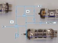
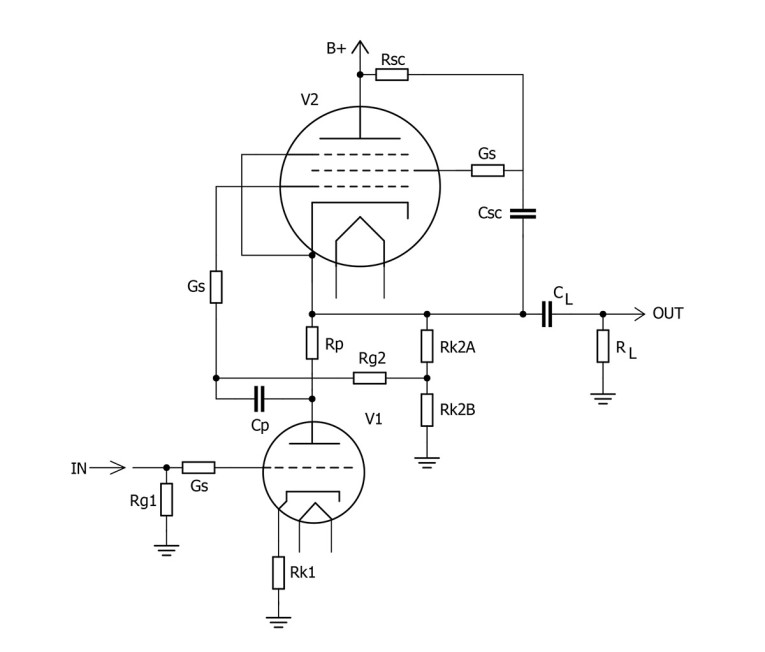
The most basic Mu3 Stage uses two chokes, L1 and L2 (which are called anode chokes). RP1 and RG2 are bootstrapped by V2 to multiply the AC resistance of RP1 and RG2 well beyond their ohmic values.
The Mu3 Stage differs from previous mu stages in several interesting ways, such as: Its supporting pentode cathode follower V2 (or solid-state unity gain follower) sits near Ground potential. And this mu stage uses two to four audio chokes. Being more efficient, it needs only about half the B+ voltage of other mu stages, yet it is capable of large output voltage swings. The Mu3 Stage is also simpler than a Type I mu stage.
Our audiophile friend Dr. Joe Tritschler (www.joetritschler.com) gives a succinct four-point description of the operation of the Fully Choke Enhanced Mu Stage as follows:
(1) It’s a classic mu stage all right, with the pentode cathode follower V2, which bootstraps plate resistor RP1 (40K resistor at V1) to get the high impedance necessary to achieve mu-stage operation of V1.
(2) Additional bootstrapping occurs across RG2 (1M resistor at V2) as its far end connects to the output of the circuit; and since its resistance is already very high as well, V1 isn’t just coasting, it’s coasting downhill!
(3) Feeding the screen of V2 at the same AC point as the far end of RP1 to achieve true pentode operation of V1 is super clever, and using L2 to get DC current into it without causing a significant AC load on the screen or circuit output is too.
(4) Using L1 to get a low-resistance DC path for sufficient current through V2 without posing a burdensome AC load on the output [or resorting to electronic current sources] is really elegant.
Speaker entrepreneur and mu stage builder Kim Bond graciously agreed to build, test, and audition a Mu3 stage. His report completes this article (see below).
Last but not least, a Mu3 stage can be modified to be a Pentriode Mu3 Stage. A Pentriode Mu3 Stage may well be as good as it gets... Maybe that will be a topic for another time. If you want to fight listener fatigue, replace your conventional audio gain stage with a Mu3 stage.

Additional Notes
Audio circuitry having one or more audio chokes or audio transformers must be kept well away from 50Hz/60Hz power supplies by having the power supply in a separate chassis. However, if the power supply is a high frequency switched-mode power supply (SMPS), then it is OK for power supply and audio chokes to share the same chassis or enclosure.
L1 in the prototype is a 50H anode choke (inductance value not critical), which can be capacitor-coupled to the output jack or to an output transformer (capacitor-coupling to an output transformer is known as Para-Feed). Or if you have an output transformer that will accept V2’s cathode current in its primary winding, then L1 can be replaced by that output transformer’s primary. L2 in the prototype is a 150H low current anode choke (inductance value not critical).
When using anode chokes and capacitors together, choose their values to avoid any LC resonance in the audio band. You can check that with the formula for Resonant Frequency in Hertz = 1/(2π√(LC)), with H in Henries and C in Farads. There may or may not be some sonic advantage in replacing RG1 and/or RG2 with a grid choke. RG1 is the 680K grid resistor at the voltage gain tube V1, and RG2 is the 1M grid resistor at the pentode cathode follower V2. As with any mu stage, a wide variety of triodes and pentodes can be used in the Mu3 stage. The Mu3 stage can be made hybrid by replacing V2 with a suitable FET or other solid-state device.
Editor’s Note: All audioXpress articles from 2001 to present can be found on the aX Cache, a USB drive available from www.cc-webshop.com.
Resources
A. Kimmel, “The Mu Stage,” Glass Audio, Issue 2, 1993.
A. Kimmel, “An Outrageous Mu Stage: An Update of My 1993 Mu Stage Design,” audioXpress, May 2019.
Tritschler Precision Engineering, www.joetritschler.com
Prototyping Alan Kimmel’s Mu3 Stage
By Kim Bond
I was introduced to vacuum tube audio in the early 1990s and built my first Mu Stage in 2004 after reading Alan Kimmel's earlier articles. Using an orphan 9AH9 triode-pentode from a TV repair caddy, my first Mu Stage was an immediate success, and I used it as the combined voltage amplifier/driver stage for a series of single-ended power amps. Over the years, I used Mu Stages elsewhere, including in phono stages, so when Alan asked if I would prototype the Mu3, all I could say was YES!
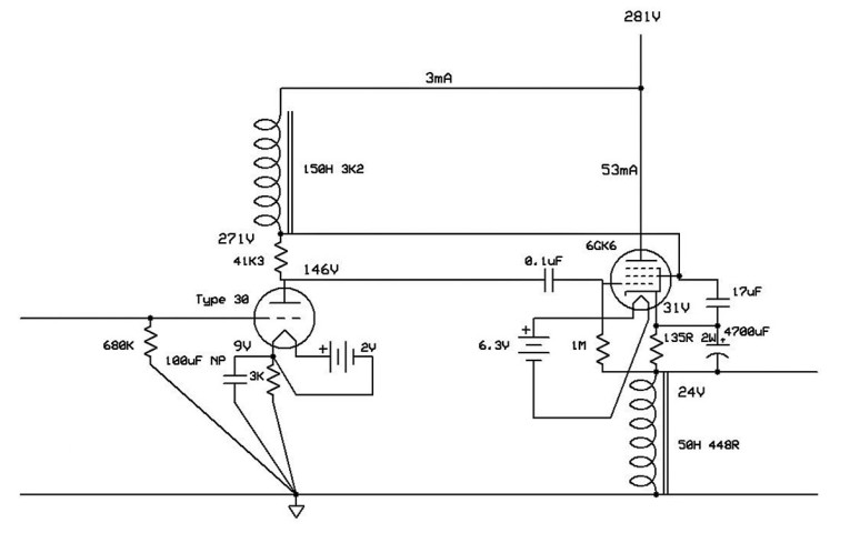
Alan suggested an arrangement for a lower voltage mu stage, bootstrapping the anode load of the amplifying triode via the screen grid of the supporting pentode, offering improved performance of both the triode amplifier and the pentode cathode-follower by using choke loads. Figure 1 shows an implementation of Alan’s idea using a type 30 directly heated triode as the amplifying device and the 6GK6 pentode as the mu-load and cathode follower.
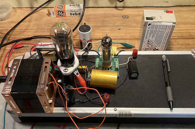
The type 30 was selected because its linearity had previously been investigated in a more conventionally arranged choke-assisted mu stage. The 6GK6 was selected because it was on hand and was electronically equivalent to the EL84 pentode suggested by Alan. Photo 1 shows the “breadboard” prototype I used to evaluate Alan’s Mu3 concept.
Batteries supplied filament and heater current and a Hewlett-Packard 6290B provided the high voltage supply. All resistors were metal film. The capacitors were: a non-polar electrolytic to bypass the type 30’s cathode bias resistor; a 0.1μF metallized polypropylene to couple the type 30 to the 6GK6; a large, metallized polypropylene-in-oil (not in photo) to bypass the screen grid to the cathode of the 6GK6; and a 4700μF Jensen electrolytic capacitor to bypass the 6GK6’s cathode bias resistor. The anode choke is a Hammond 156C. The 50H cathode choke is rated for 100mA and was made in Taiwan by Vintage Audio Labs.
Measured Performance
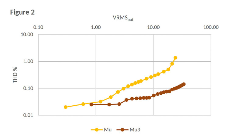
Figure 2 shows the percentage of total harmonic distortion (THD) of the type 30 in the Mu3 stage compared to the same tube type in a more conventional choke-assisted mu stage. Distortion was measured as a function of output at 1kHz. The test signal was provided by a calibrated Keithley 2015-P, which also took the measurements. The distortion from the Mu3 stage (brown) is an order of magnitude lower than the more conventional choke-assisted mu stage (yellow).
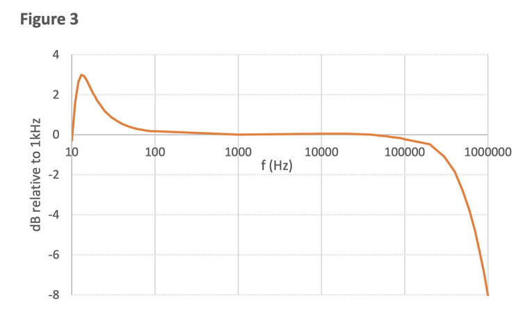
Figure 3 shows the frequency response for 3.5Vrms out (driven by a Hewlett-Packard 651A test oscillator) to be -3dB at a bit over 500kHz.
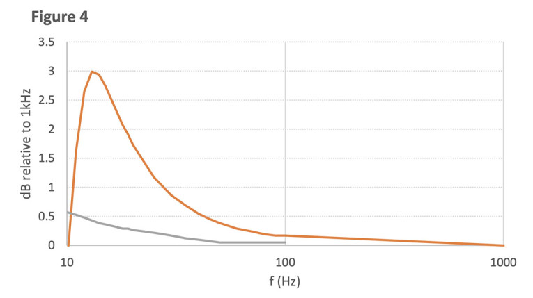
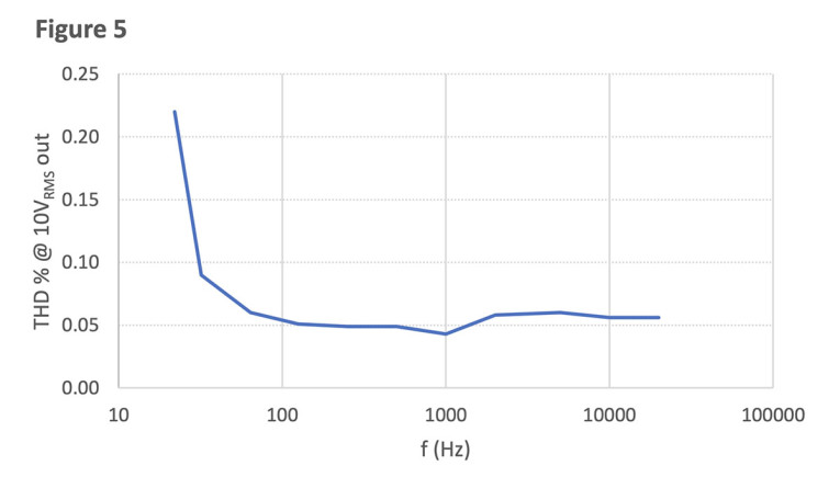
The low-frequency peak arises from the resonance of the LC circuit formed by the 6GK6’s screen bypass capacitor (3.3μF for the measurement shown) and the 50H cathode choke. Increasing the size of screen bypass capacitor to 17μF lowered the resonant frequency, as shown by the grey trace in Figure 4. The frequency dependence of distortion at 10Vrms out is shown in Figure 5.
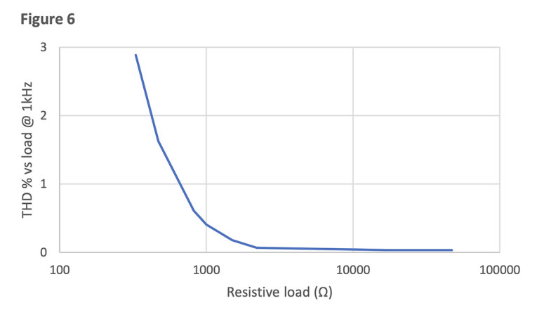
The measured output impedance at 1kHz was less than 150Ω. Driving performance was assessed by measuring THD at 3.5Vrms out as a function of resistive load, shown in Figure 6.
Discussion
The breadboard prototype has excellent measured performance. Distortion is very low down to the noise floor and could probably be improved by better layout. Bandwidth is substantial — the low-frequency response must be adjusted to suit the cathode-follower’s choke load and screen bypass capacitor. Drive is very good, with low output impedance, less than 0.25% THD at 20Hz and10VRMS out, and less than 0.1% THD for loads greater than 2kΩ.
The 4700μF cathode bypass capacitor used in the prototype to prove the concept was later replaced by a smaller 100μF non-polar capacitor—there was a little roll-off in the frequency response below 80Hz (less than 1dB) countered by the 17μF screen bypass capacitor. Builders may wish to experiment with the values of these two capacitors to tailor the low-frequency response.
Listening Impressions
The breadboard prototype was auditioned for a total of 10 hours on two systems. A small workshop listening system was used to assess experiments. It comprises a small Sony CD player, a passive stepped auto-former volume control, and a very small valve amp (direct heated triodes, less than 1W) driving 10” full range speakers in floor-standing bass-reflex cabinets. The Mu3 breadboard was inserted after the volume control, configured to receive left+right channels, amplifying to deliver dual mono to each of the left and right channels of the power amplifier.
• In this system, the Mu3 has no sound of its own, just gain.
• The strength of this system is detail—the Mu3 preserves that in full.
• It does not change the “sound” of the small system at all, just makes it louder.
• This is not a null outcome—all other preamps previously inserted into this position changed the sound of the system.
• The Mu3 didn’t change the sound of this system over two hours of listening.
The Mu3 was then auditioned over three sessions for eight more hours on a larger system. Sources were a CD transport and a DAC, and a turntable with a moving magnet cartridge and a phono preamplifier. The volume control was a stepped autoformer, supplying four channels of push-pull KT88s in ultra-linear mode. The bass-reflex speakers each received two channels of drive from the power amplifiers in a form of bi-amping. This system was configured in a 25m2 (270ft2) room. Along with clean detail, it delivers extended bass. Music that sounds good on the small workshop system is “filled out” by the larger system.
The Mu3 has no negative effect on the excellent mid-range of this system — it is unchanged so that the instruments or vocals retain integrity. The top end was “filled in” a bit more — this system uses ribbon tweeters—and sounds more interesting. This may contribute to the perception of more micro detail in the mid-range, with the caveat that the reviewer is in his 60s and cannot hear sine wave tones above 13kHz.
The most perceptible change was to the mid-bass and bass. The capability of the larger system is limited by its physical layout, with long cables connecting the auto-former volume control to the power amps, interposing extra capacitance. The Mu3 has no difficulty driving the cables and the timbre of acoustic bass is distinctly improved. The tone of electric bass is improved to the point that one artist's bass amplifier could be distinguished. Electronic bass has additional "weight."
These impressions were the result of three listening sessions, all in mono. Stand-out tracks were from Junior Wells’ “Hoodoo Man” mono LP, Yevgeny Mravinsky’s 1981 stereo LP of “Shostakovich’s 4th symphony,” Archie Roach’s stereo CD of the soundtrack for “The Tracker,” Dawn Upshaw’s stereo CD “The Girl With Orange Lips,” Sviatoslav Richter’s 10” mono LP of “Mussorgsky’s Pictures at an Exhibition,” and Massive Attack’s stereo LP “Protection.”
Conclusion
Previously, I’ve used preamplifiers of various topologies and technologies in the big system — all were eventually removed so that over time, only stepped autoformer attenuators remained. The Mu3 is the first line level preamplifier that I have used that has excellent measured performance and does not perceptibly alter the sound. In the case of the big system with its awkward cabling, the Mu3 improved both the lows (mid-bass and bass) and the highs (perceived micro detail).
It is encouraging to have at hand a preamplifier topology that allows greater flexibility in system gain structure. Upstream, a quieter but less sensitive phono stage becomes practical. Downstream, a less sensitive power amplifier with greater margins of overload might be used.
The simplicity of the topology supports experimentation with different low-gain direct heated valves (such as the type 30, the type ’01A, or the triode-strapped 6A4/LA), or indirectly heated valves (such as the triode strapped 6G6G or 6V6). Higher gain valves might also be used.
The Mu3 prototype is a technically proficient preamplifier circuit with good drive that delivered good music without interposing any particular sound or “signature” of its own. A full stereo version will now follow. aX
This article was originally published in audioXpress, May 2025
The author appreciates any comments about this project. Contact Alan Kimmel here.