The Circuitry
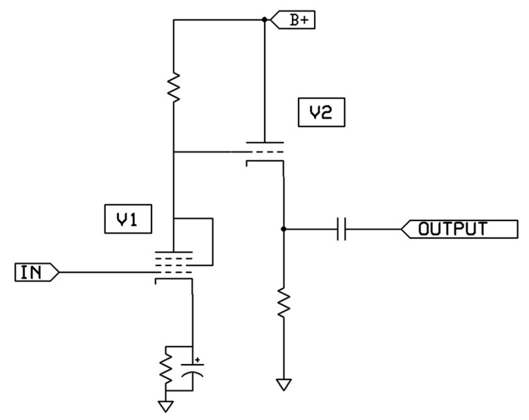
Probably everyone who reads anything about tube audio circuitry knows that a pentode can function as a triode when its screen grid (Grid 2) is connected to the plate — see V1 shown in Figure 1. When triode connected, many pentodes can be outstanding very linear triodes.
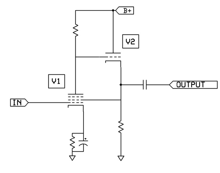
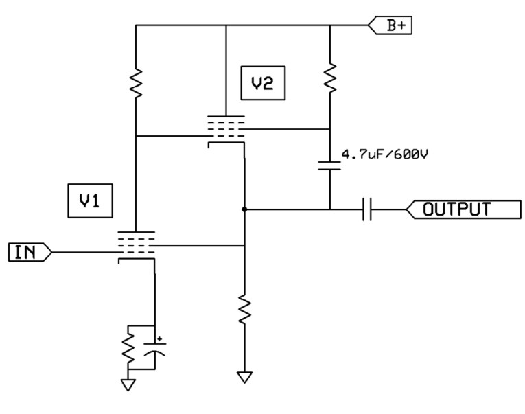
The Pentriode is formed by making one simple change to Figure 1: Connect V1’s screen grid, not to V1’s plate, but to the cathode of cathode follower (CF) V2—see Figure 2. In Pentriode mode, V1 essentially operates as a triode, but its screen grid current no longer burdens the plate of V1. Instead, CF V2 provides all current to V1’s screen grid. Pentriode mode brings nice advantages.
Pentriode mode is not strictly triode mode nor is it pentode mode. It is also not “ultra-linear” (aka partial-triode) operation. I had to come up with an entirely new name for this circuit, and the name Pentriode seemed appropriate. Pentriode mode is definitely most like a triode mode, with the same (or closely the same) mu and gain as the pentode would have in conventional triode connection. In fact, designing a Pentriode stage is as simple as designing a standard triode stage, the only extra part being the addition of a simple cathode follower.
Cathode follower V2 can be any active device, including a triode CF or a pentode CF (my favorite follower for audio — see Figure 3). There are also several other options: You could make a hybrid Pentriode by using a field-effect transistor (FET) source follower in place of V2, or a bipolar junction transistor (BJT) emitter follower, or a Darlington emitter follower, or an insulated gate bipolar transistor (IGBT) emitter follower, or a Sziklai pair follower, or an IC voltage follower, or a current follower, and I’m sure several other follower types. V2 could also be a follower consisting of a vacuum-state device, solid-state device, gas-state device, or any state device.
By the way, it is my standard practice to use grid stopper resistors for every control grid and every screen grid. Suppressor grids don’t need a stopper resistor. In audio applications, I normally use a value of 220Ω for grid stopper resistors.
Pentriode’s Benefits
It is important to note that some pentodes really excel in Pentriode mode, more so than other pentodes. Some pentodes give even less distortion in Pentriode mode than when the pentode is connected in standard triode connection. It would be nice if we could tabulate a list of the pentodes that excel at Pentriode operation.
It is also possible to make a Pentriode mu stage, which is probably my favorite type of mu stage. It has all the advantages of mu stage operation including wide bandwidth (BW), low distortion, low output impedance, plus the advantages of Pentriode operation. A practical example is shown in Figure 4. With regard to Figure 4: 1) The purpose of the 27kΩ resistor is to drop a few DC volts so that V1’s screen grid voltage is the same as V1’s plate voltage, to closely emulate triode operating conditions for V1. 2) When a 6AC7 tube is used for audio, its heater is best powered by DC. 3) The heater of V1 is pins 2 and 7; the heater of V2 is pins 2 and 7.
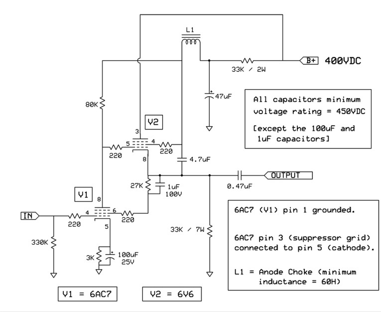
Here are a few notes for every schematic in this article: 1) The heater supply of V1 should be grounded, but the heater supply of V2 should be floating. 2) The DC voltage at the cathode of V2 should be in the neighborhood of half B+. 3) For clarity of the schematic diagrams, the suppressor grid (G3) of every pentode is shown not connected to anything, but do connect G3 to the pentode’s cathode.
Practical Application
I have a friend who is a triode fan, and I modified his stereo single-ended triode (SET) amplifier by converting its voltage gain stage into a mu stage, and he was thrilled with the increased realism and musicality that brought to his amplifier. But I took it a step further and also installed a switch that lets him switch between triode mu stage and Pentriode mu stage operation, but I did not tell him the switch positions—I only told him that the switch gives him two different amplifiers. (Note that such a switch must be switched only when the circuit is OFF and COLD, to avoid sending a large THUMP into the speakers.) I asked my triode fan friend to audition his modified SET amplifier and tell me which switch position sounds best to him. He reported that he prefers the switch position that happens to be the Pentriode mode!
Overall Assessment
In conclusion, listening tests as well as measurements show that Pentriode operation can be superior to either pentode or triode operation. If triode gain is all the gain you need in your application, which is often the case in audio, I believe that the Pentriode may well be the ultimate triode for the reproduction of music!
This article was originally published in audioXpress, May 2022
 About the Author
Alan Kimmel has been interested in electronics ever since he was introduced to home-brew stereo systems early in life. He enjoys inventing vacuum tube and solid-state audio circuits, as well as non-audio inventions. He has an A.S. degree in Electronics, and an A.A. degree, but is largely self-taught. He can be reached by email here.